article
F4U-1A Corsair By: Hubert Ortinger
My Project Tamiya 1/48 scale
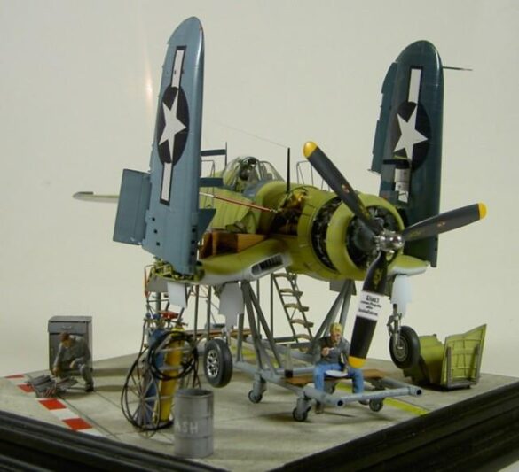
Having outdone myself with my Wildcat with folded wings and a highly detailed kit, I intended to do the same with this Corsair, so I wanted to detail the gun mounts and folded wings. However, since every famous modeler has already built a “common” F4U, I wanted mine to be a bit special and unusual.
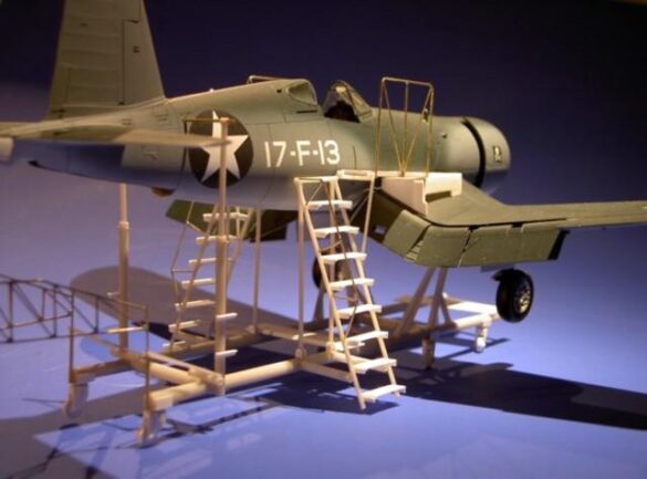
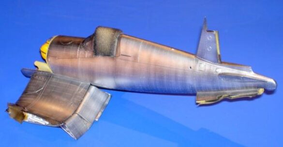
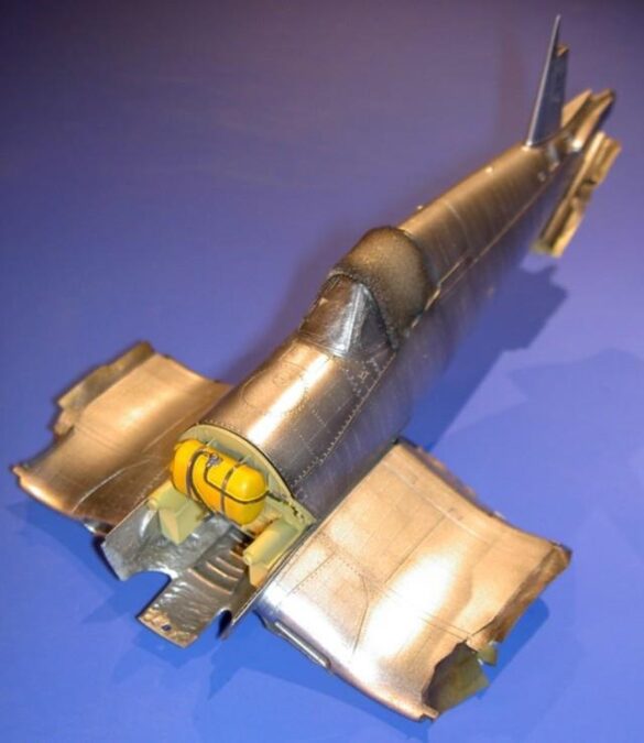
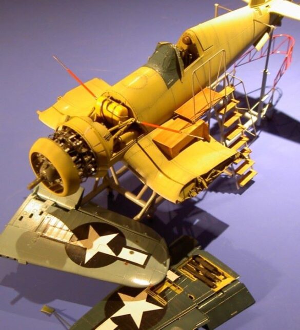
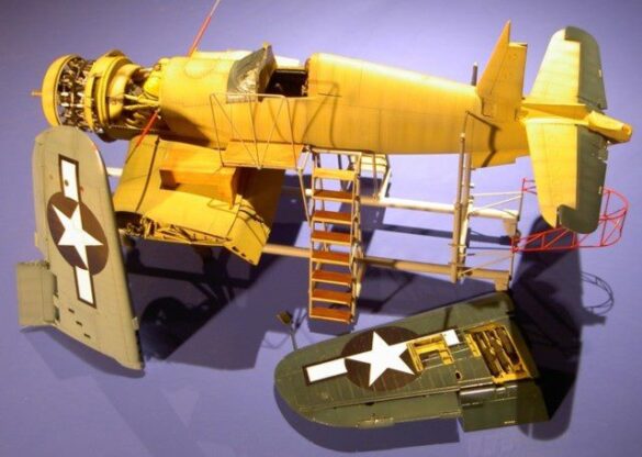
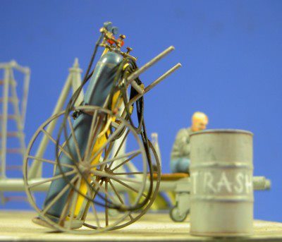
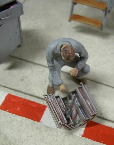
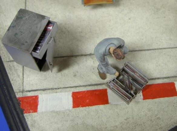
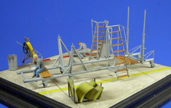
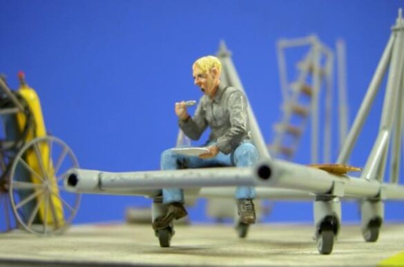
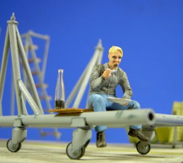
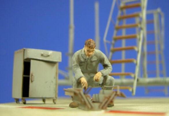
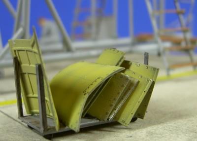
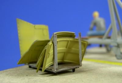
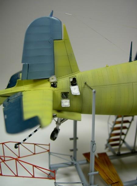
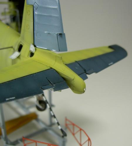
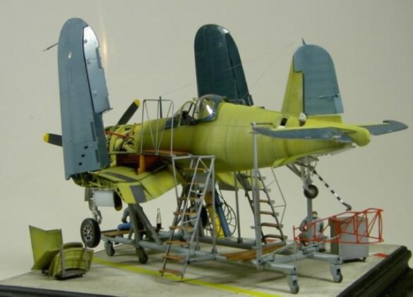
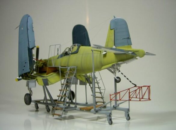
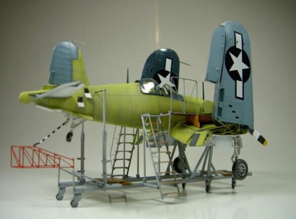
My decision was to depict an unfinished airframe on the assembly line based on a photo in the Squadron publication “Corsair in Action”.
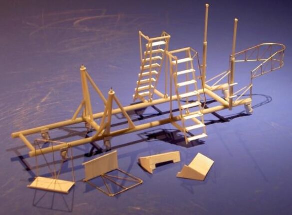
But how should I build the factory assembly jigs?
Construction
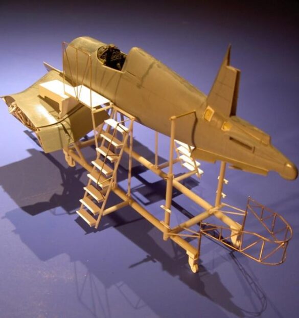
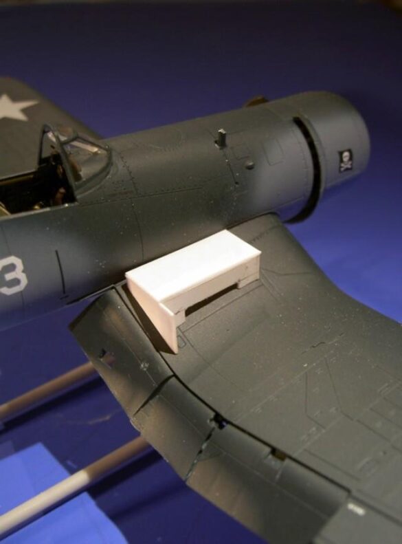
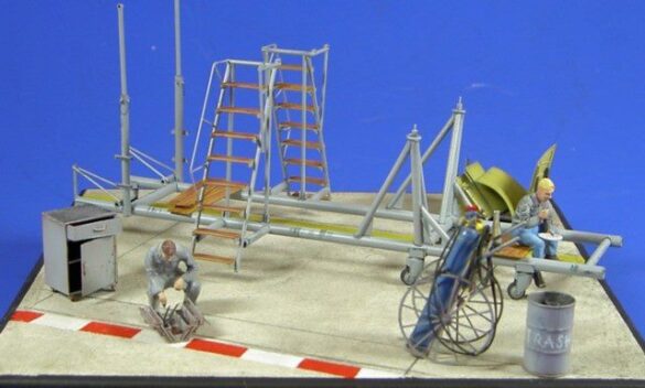
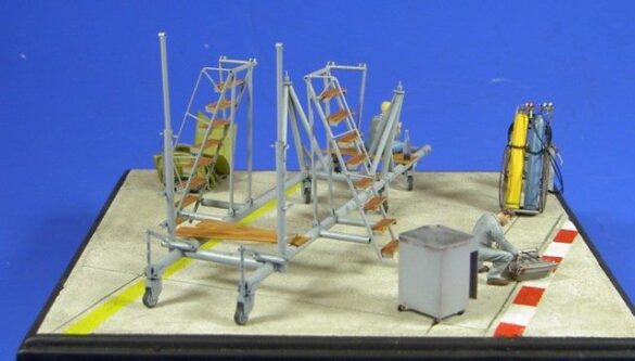
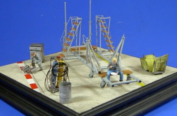
The Assembly Jig
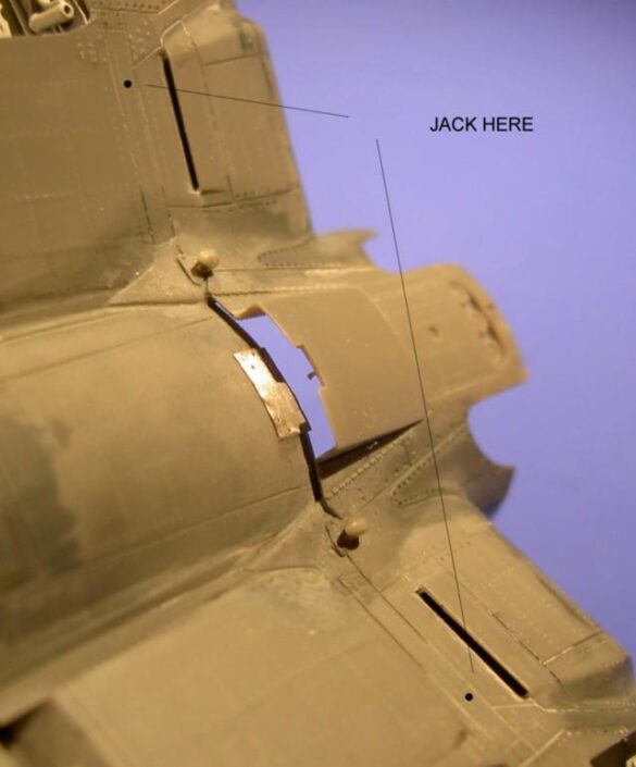
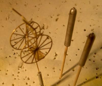
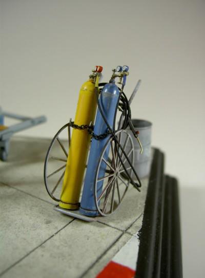
First I made various sketches on copied 1:48 sidecuts and searched countless photos for the exact “Jack here” position for lifting on the undersurface. After many unsuccessful attempts, I finally had the brilliant idea and succeeded in making the cylinders from plastic sheets of different strengths, and this six times, because I had no idea they would leak.
Huge quantities of plastic profiles are mixed until finally “gluing” the frames including the beams with “superglue”. A model of the same type built in earlier times had to help me find and hydraulically install the correct measuring instruments.
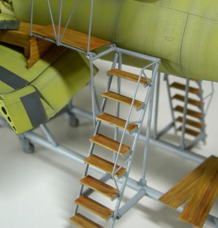
I reinforced the base frame with a metal tube because the weight of the airplane and the emphasis of the final model should not be underestimated for safety reasons. Also, the gauges of the platform that would be placed on the wings had to be designed and the estimates determined and then carved and glued from the sheet.
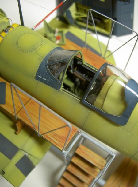
I glued the stair handrails, the bridge railings and the tail safety loop from curved brass wire. A subtle wooden construction from the appropriate parts was depicted by pulling over sandpaper.
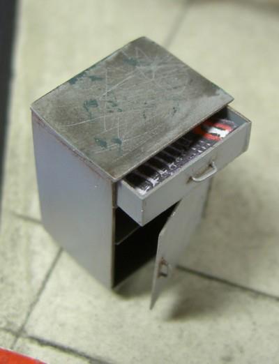
I sprayed everything in Revell semi-gloss gray, so I opened the longer tubes centrally and all the weld seams were made flush. The paint wear on some corners and edges was painted dark gray to give a used look.
The safety loop was painted red. For the wood grain I looked to the World War I modelers, who use this technology with their cases. The parts were primed with sand and leather colors. After a long drying time I took brown oils and painted with an old brush a raw wooden structure on it which I wiped after a few minutes with a cloth moistened with lighter fluid again.
Sounds easy – it is also easy!
As the result was very small compared to the high contrast plane, I later repeated the whole process with Vandikbraun once more.
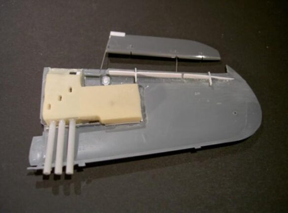
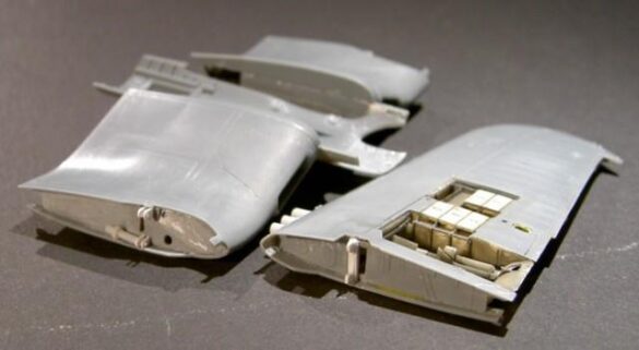
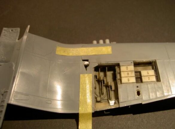
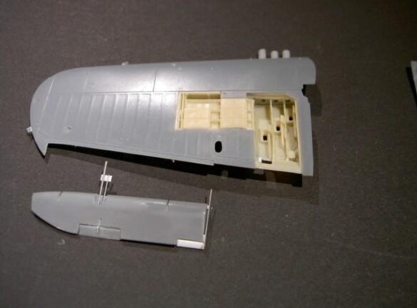
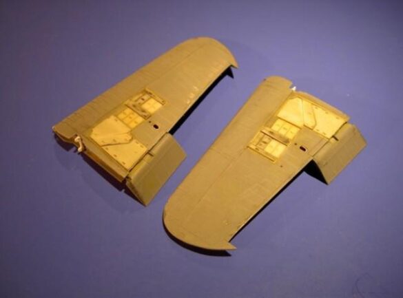
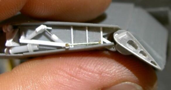
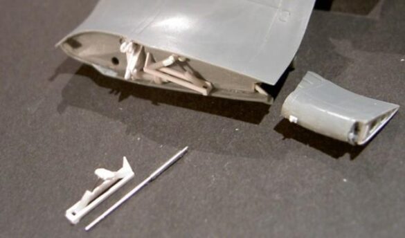
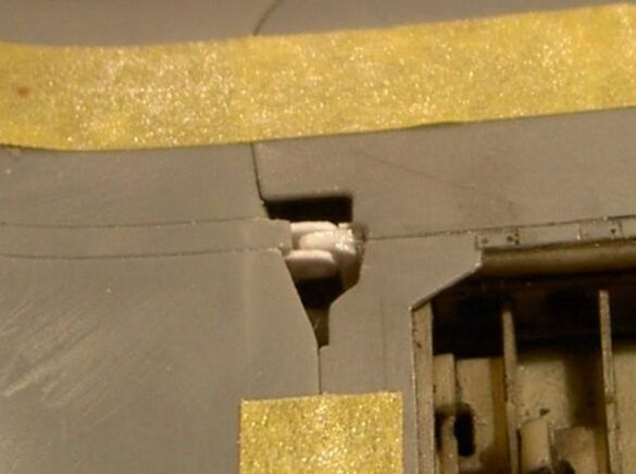
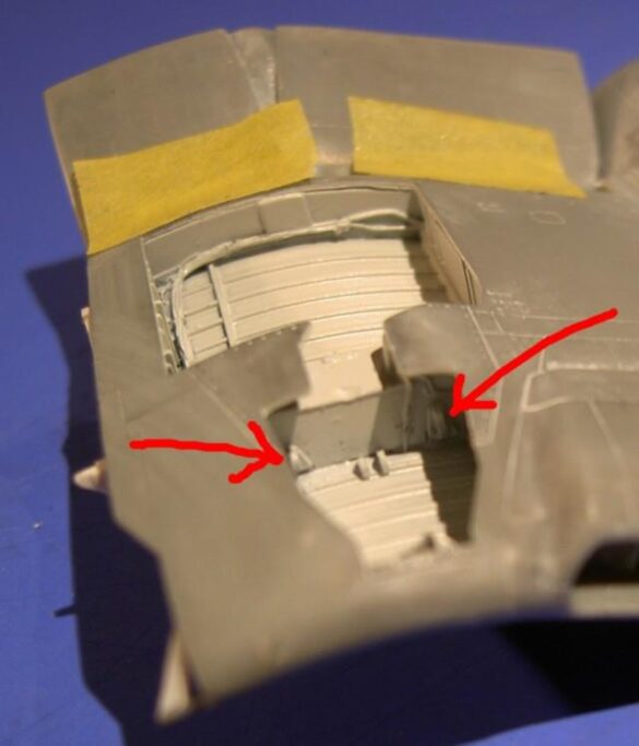
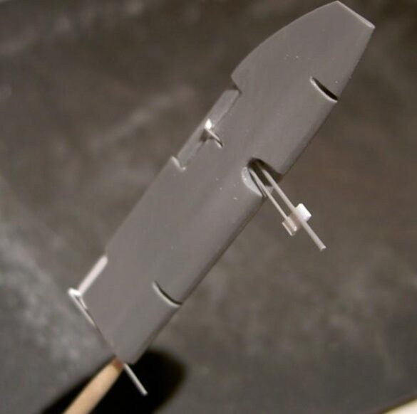
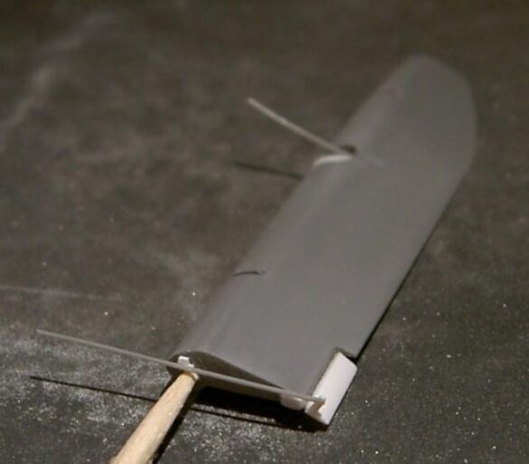
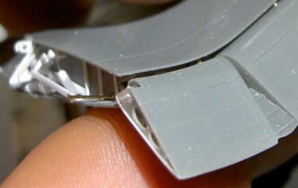
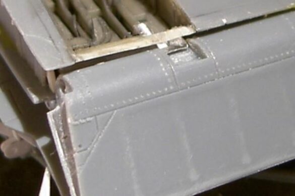
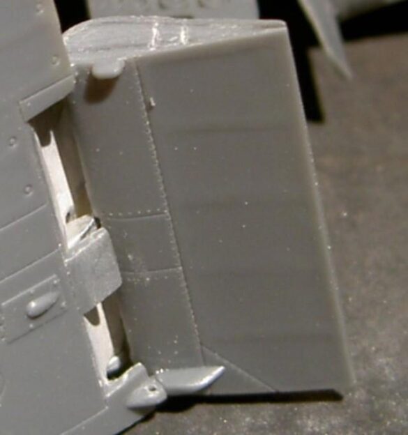
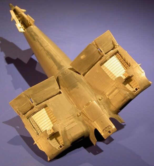
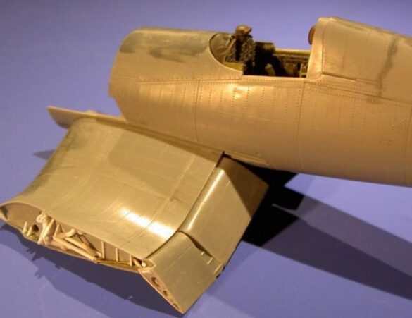
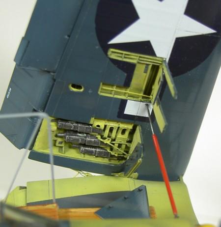
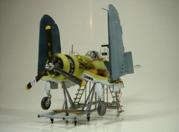
I started to settle in with the wing areas, the most important part for me, because I wanted the wings to not only fold but to stand upright to look at both the folding mechanism and the weapon holsters. The Tamiya hinge layout for this option was wrong for that, however both the Resin wheel wells and the Resin weapon wells had to be inserted in a way that was largely useless there. The junction had to be completely sanded down and the mechanism had to be made as well as the hinges from Evergreen material. Since I didn’t know how to give the whole build sufficient stability at the moment, I still thought about it, but it was clear to me that I would have to do it like the original.
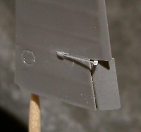
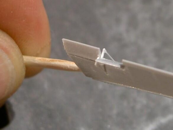
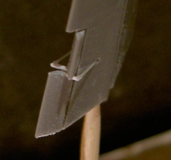
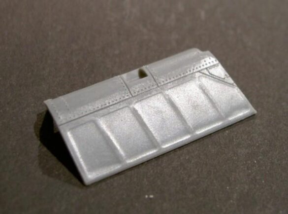
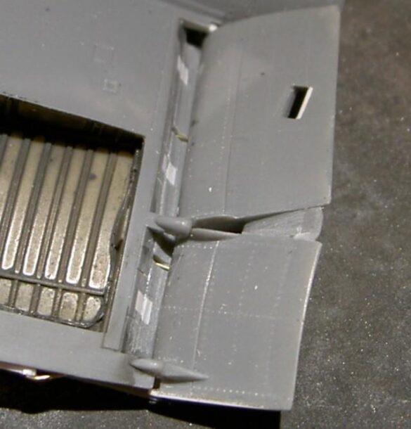
The special Aires parts fit perfectly after milling the necessary position and sawing the appropriate parts (flaps). For easy installation of the MG and to make a more beautiful transition of the openings to the leading edge of the wing, I used suitable plastic tubes. The flaps and also all other control surfaces were of course cut out and exchanged with their own from Aires. In addition, all trim tabs were also modified. After I put a feed and hinge mock-ups to hide the view inside, the wings could be glued. The position lights on the wing tips were sawed off and replaced with transparent plastic. The clumsy pins on the landing flaps that are attached separately in the kit were unstuck and I only attached them to the joints and small pieces of wire. However, this does not look so solid for it, but it turned out more filigree and more original-faithful.
The holes in the wing had to be closed then with plastic. From the heels of the catapult I was not inspired – I cut them off and made it scratched.
Everywhere something was filed and replaced and there were probably not many parts that were not changed and did not have any detail in any way!
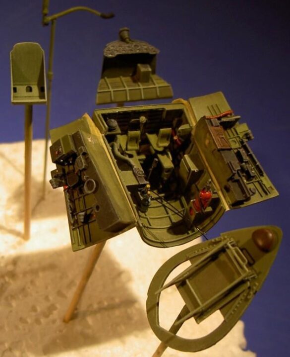
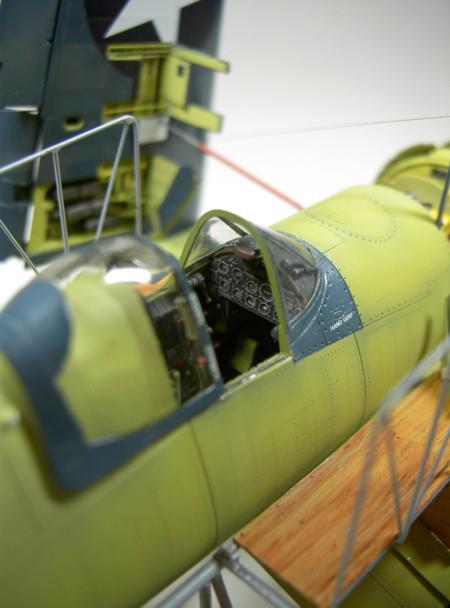
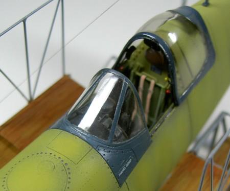
With the cockpit, for example (a real gem), I wanted to be able to look better inside, so the seat had to be developed. The basic seat stand is stupid-it turns out to be cast and must be designed for my requirements and adjusted to the back.
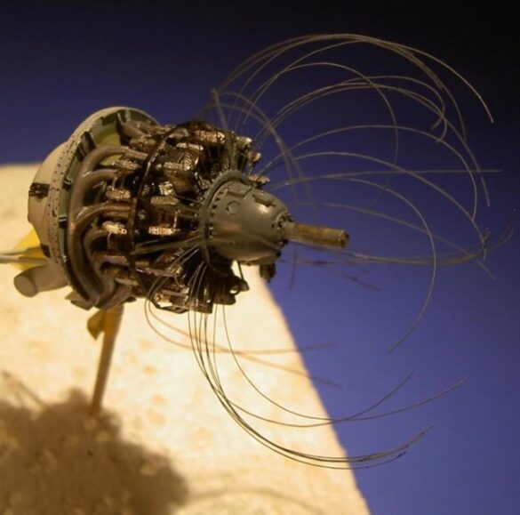
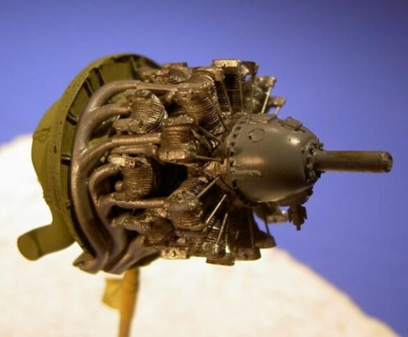
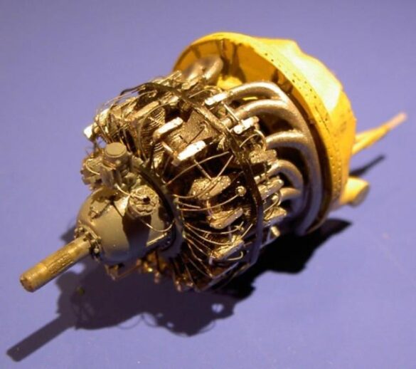
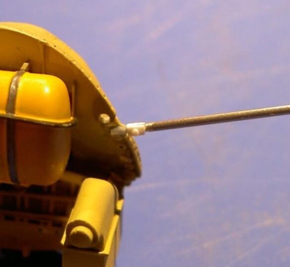
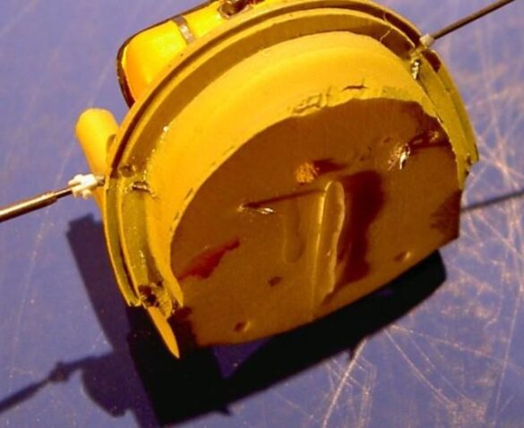
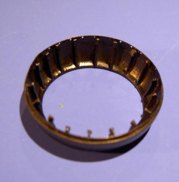
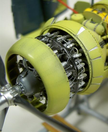
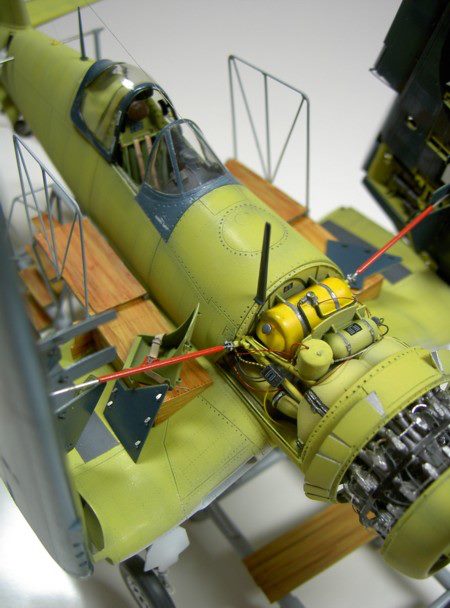
The engine is a kit for itself, but still needs a lot of pre-emption. I added the ignition wires with thin fishing line and detailed the ring that leads them to the cylinders and at the same time keeps them away from the heat. The painting of the unit was done on the leg and proved to be quite a challenge because the exhaust manifold joints were already glued there. It is worth noting that I should not lose sight of the fact that I ultimately wanted to represent an airplane fresh from the factory, which made things even more complicated.
That means low-key weather conditions!
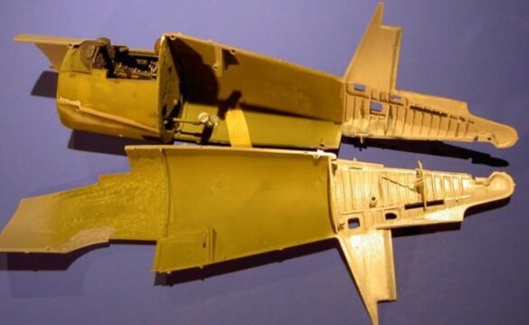
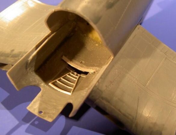
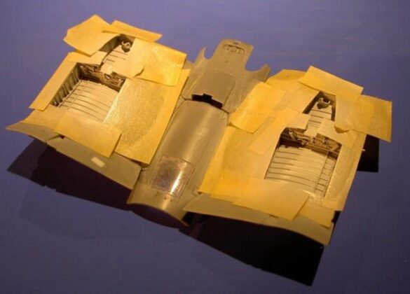
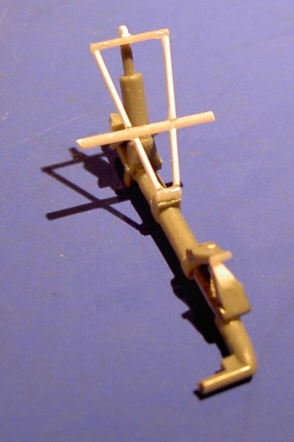
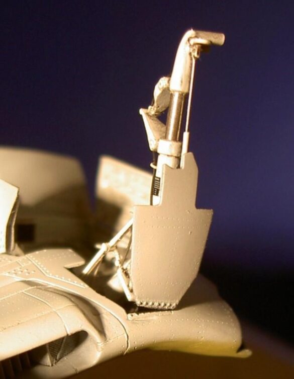
It was still a long time before I was allowed to glue the fuselage halves, I also wanted the service covers for the tail landing gear to open there and therefore I copied the complete drawing into the mechanism for this. I prepared the construction in such a way that I had nothing to do but put it in after painting. I did not replace the acceptable tail landing gear doors, but I detailed a closing mechanism for the model.
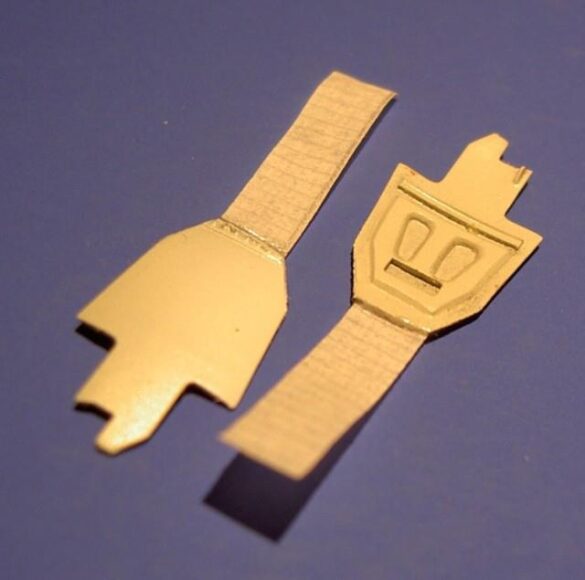
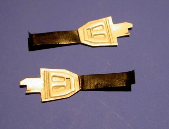
In the pictures one can recognize the plaintiff’s expenses better than I can exploit in words.
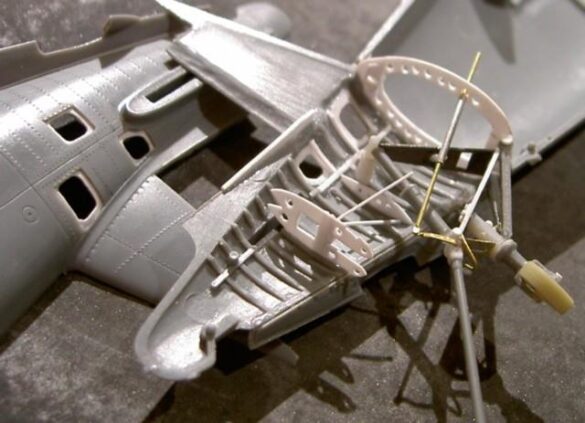
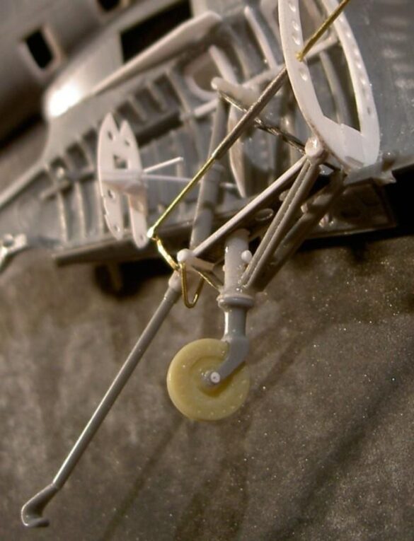
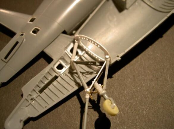
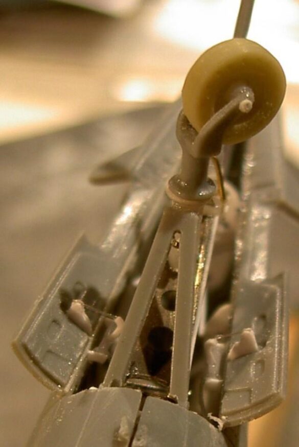
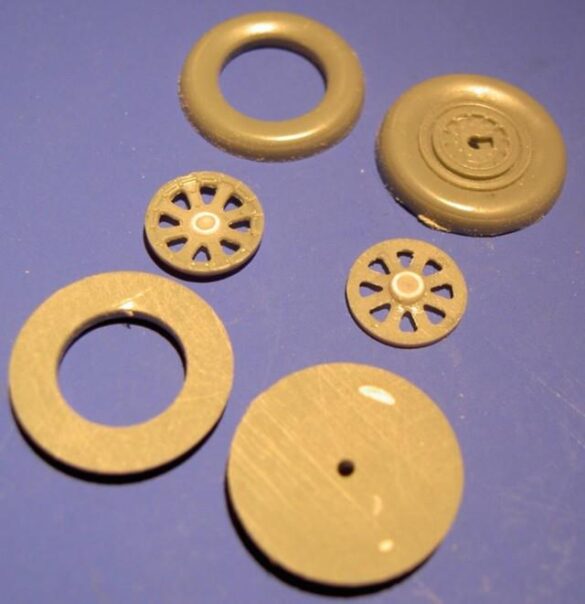
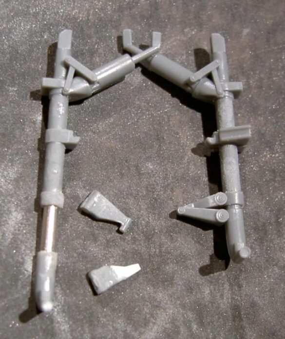
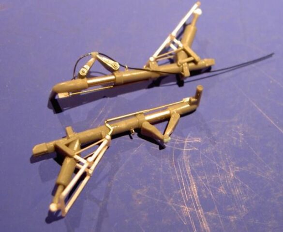
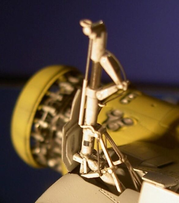
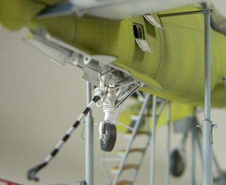
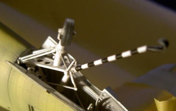
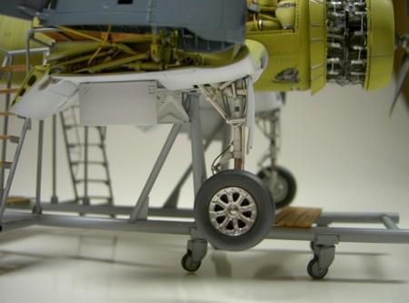
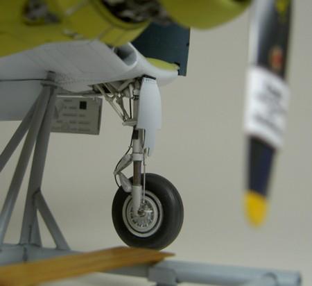
I occasionally used the main landing gear which required exactly the same attention from myself. Tamiya designs a loaded chassis, but still my plane hangs in the air because I had the frame leg to look extended. In addition, I first cut the wing/spring strut, replaced the damper pistons with a metal pin and glued it very open. Also the mechanics at the front, which turns the wheel when pulling by 90 degrees is missing from the kit frame and needs to be added. My wheels looked very thick, because I took them apart, filed them thinner and glued them back together. Then there was no profile, so I decided to try something I had often seen:
I painted the wheels anthracite, covered a groove profile and painted dry with bright gray. An amazing result adapted itself!
On the individual rims I sanded so much until the plastic between the spokes was discharged. Although the plastic parts of the kit for the main landing gear traction mechanism are not bad, but they do not fit the model’s connection to the Aires resin landing gear. Away! The reconstruction looks even more filigree. Above stability I did not have to think!
Rosie the Riveter
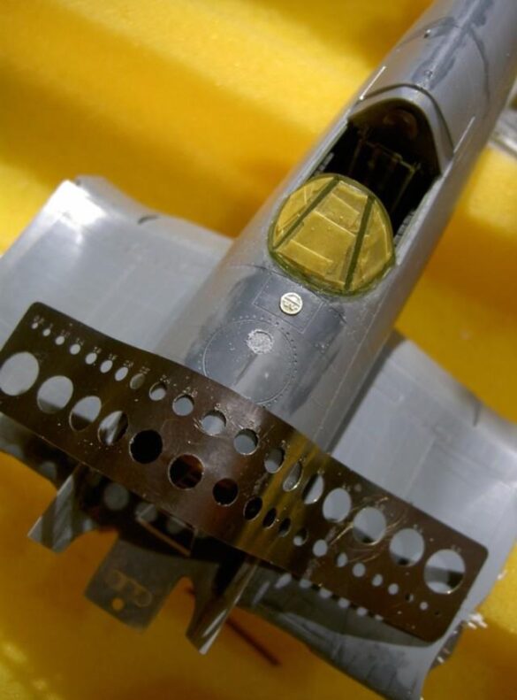
I recently bought the “Rosie the Riveter” and finally decided to give it a try. Before joining the fuselage halves, I studied the surface of the plane and marked with a pencil, using model photos, a little logic and some imagination, the structure of the rows of rivets on the surface of the model. I practiced handling the new instrument on cast-off parts until I was finally ready. I extended the handle with light pressure following the lines. The very time-consuming task requires concentration, above all in the milled parts the plastics were very thin or with splices, which burst with excessive pressure again pleasantly. For several hours I did nothing else to pierce my model.
I didn’t think I could handle the “stressed skin” on sheet metal, which was going to be damaged, but the original surface was pretty smooth anyway due to the new spot welding process.
After sanding with the best flies, I was allowed to glue the fuselage and the bottom together. On the inside I detailed the fin for cooling the compressor before fitting the fire wall with the oil tank.
In this context now also the fitting for the supports for supporting the outer fins in the folded state, which led me to the idea of fastening them in such a way that they could take on a basic function for the wings themselves. I drilled holes diagonally backwards in the essential resin part of the baffle, placed on 0.5mm steel wires which were bent at the back and prevented from twisting in the holes with epoxy glue. The bar was bent at the right angle and detailed according to the kit part and/or the original. The folded wing is not only supported by this construction afterwards but is also properly carried by the bar!
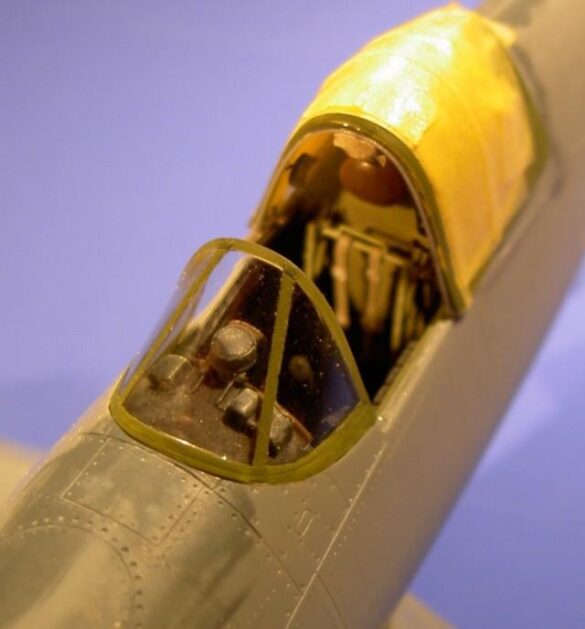
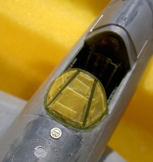
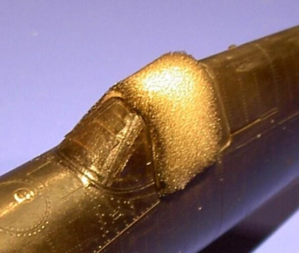
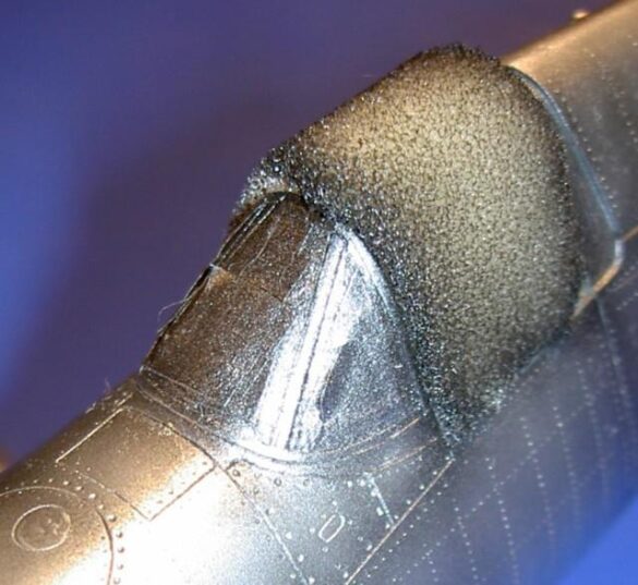
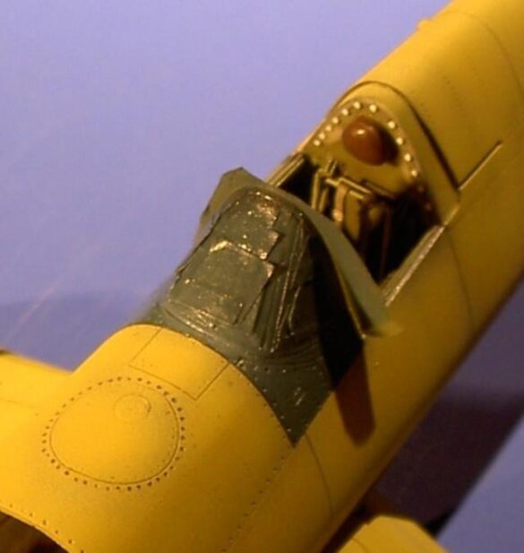
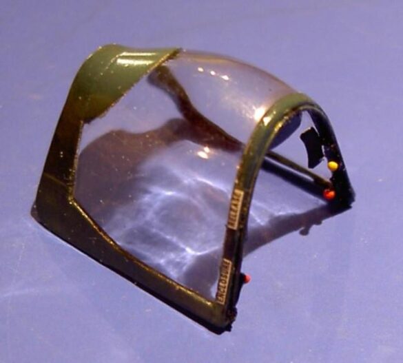
Then I took care of the transparent cockpit glass which I always paid special attention to. In addition, I first paint the window support freehand in the color of the cockpit interior and fix the windshield with plastic glue to the back of the trunk. Then I cover the appropriate rows with a small amount of Tamiya rigid tape and embed the build unit with a second adhesive, where any incorrect engravings can be filled in.
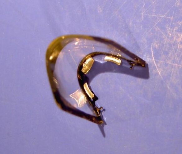
After sanding, these panel lines were etched correctly. With the sliding canopy I still detail the levers for the lock and three rearview mirrors which were disguised with chrome sheet metal on the inside. Not enough with that at the entrance I also etched the grooves in those that pushed the canopy back and forth.
Before I could put myself in the engine as a unit with its aggregates in the front part of the fuselage, I had to paint the fuselage.
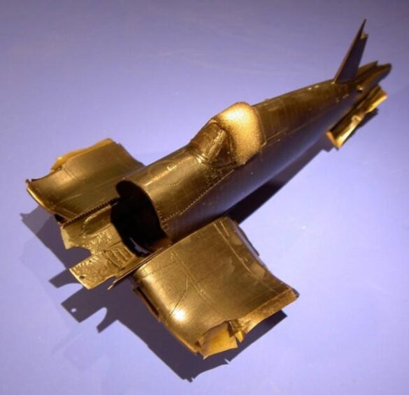
An assessment of the available reverence material led me to the judgment that this series including all the construction units as well as the fuselage was to be painted in untoned zinc chromate. Since I only wanted to do a thin glaze like on the original, I first primed its entire surface in glossy black and followed it with a thin layer of Alclad “white aluminum”. I sprayed the metal color and the following extremely time-consuming panel by panel, so that the effect was affected. Finally, the panel lines should be recognizable without washing. Since I now applied chromatic-yellow to surfaces of different colors that I had painted before, this adapted to the principle mentioned: The result was many different yellow tones!
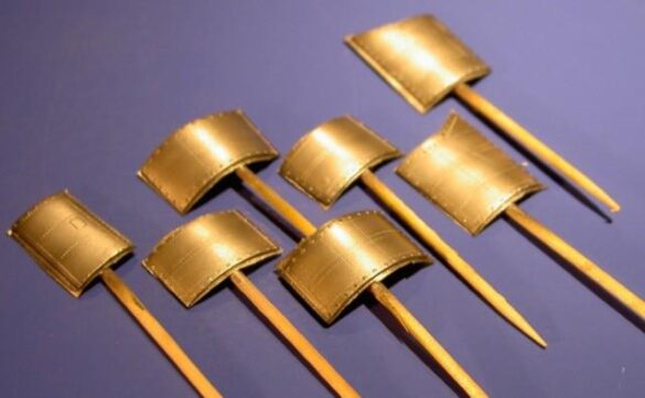
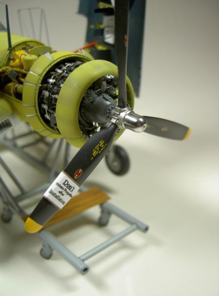
The engine installation once again required all my attention, so the exhaust pipes had to be fitted into holes in the bottom surface, cut for this. The cover, contrary to the guidance of Ayres, had to be fixed to the cylinders, so even before painting, sixteen crescent-shaped support plates were drilled and glued on the inside. On the outside, the appropriate rivets for this had to be drilled.
Painting and Marking
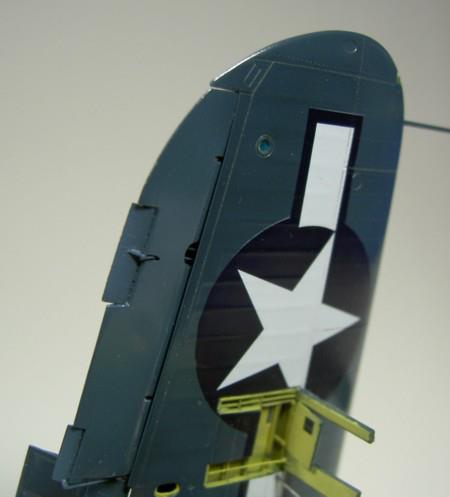
As recognizable in the original photo, the outer areas of the wings, the control surfaces of the altitude and vertical stabilizer and the canopy were already pre-coated, and so I tried to recreate this process on the model as well. I went without the metal primer, but did the yellow protective coat. I sprayed all the fabric surfaces gray. I mention here once again that I proceeded so meticulously, because I had to represent an exterior fresh from the factory and I wanted to do without washing! For shading on the upper side of the wings I used the clear and clear color, then I lightly opened the panels. For the structures of the rudders and the fabric parts I opened this clay/tone again and then shaded with it the engravings on the undersurface and the horizontal tail. Also this intermediate blue was lightened twice. With the undersurface, the wing tips and the central part I started with light gray semi-gloss and shone with bright white to reach more depth here too. As a result of toning high gloss “glossy sea blue” with semi-gloss white a not very reflective finish was obtained, and also the semi-gloss “Intermedia Blue” still offered a smooth enough surface for perfect application of the Decals, which I cut sharply around anyway. Since after a polishing with “Micromesh” the gloss level was almost the same, I could save on waterproofing.
Final Assembly
This involved welding the control surfaces into angular positions, fitting the landing gear components including the drag mechanisms and stripping the brake pipes of black painted cord. After inserting the cannons and gluing the gun and ammunition pit flaps outwards, the flap areas could finally be aligned vertically upright and secured after a detailed engineering of the screwing device. I didn’t just put it on, but I bolted the canopy front and rear with tiny taps to the guide rails.
The engine compartment was still wired with different colored wires and where it seemed necessary and possible, I glued various maintenance plates.
After lifting, I gave a propeller blade a label with the “Window Word”: “Don’t rotate…”
Vought F4U Corsair Factory Assembly Line

