article
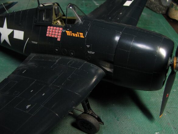
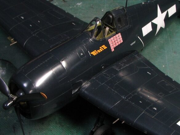
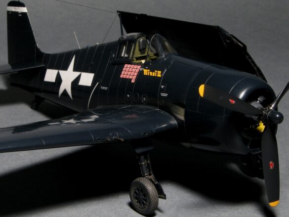
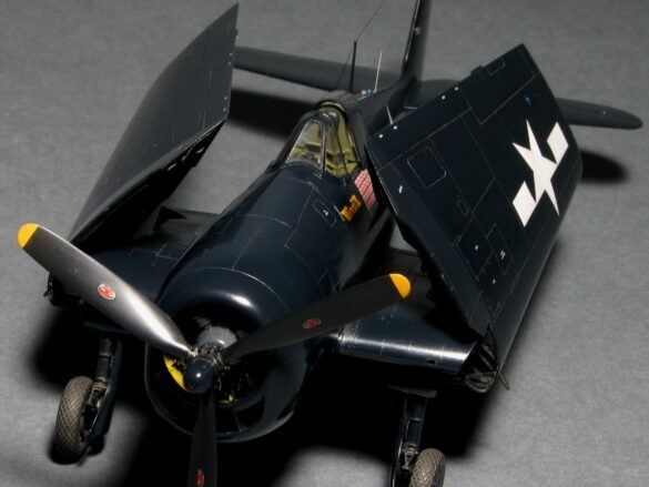
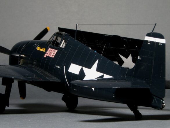
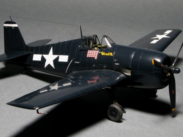
F6F-5 Hellcat “Minsi III”
Many people say; “The Hellcat was a solid war machine, but a bit mediocre”. And, I think most Hellcat models reflect the same tone. The Hasegawa Hellcat 48th scale kit is a bit boring, so it’s mediocre for me too. The Eduard kit is sharp but doesn’t capture the tough, rugged and powerful look of the Hellcat.
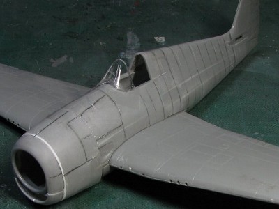
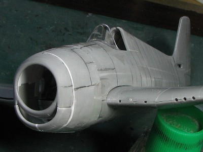
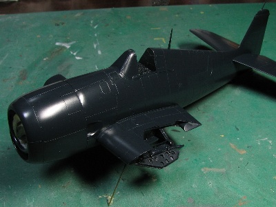
In this project, the main theme is: Fully reproduce the true contour shape of the Hellcat and portray the sharp, tough, tough and vicious presence of the Hellcat!
The second theme was a wing folding trick. To me, the Hellcat is quite spectacular at a model show, so I flashed. if the wing folded, it’s spectacular. There were two tasks. One was to ensure compatibility between the accuracy for the scale model and the ability to fold the wings. The second was; keeping the wings rigid, folded and extended.
Kit Review
Honestly; the Hellcat has not been well represented by any kit. There is no Hellcat kit that captures its true shape. Personally I think the Hasegawa 48 scale kit is the best, but it is not complete. The fuselage length is 3mm (0.12″) short, the shroud is round and the canopy is low and wide. Also, the absolute thickness of the center wing area is consistent with the real aircraft, but the kit wing is tapered.
The Eduard kit is new, but its shroud is very square. The windshield and canopy are very well shaped. Incorrect, so it does not depict the wide flat area like the real aircraft. Also, the position of the main wing is 1mm (0.04″) too low and the center wing thickness is the same as the Hasegawa kit, tapered instead of consistent like the real aircraft.
The Otaki 1/48 kit looks similar to the Hasegawa kit and some say that the Otaki “Cat grin” is better than the Hasegawa, but overall I think the Hasegawa 48 kit is superior in basic shape. Hobby Boss 1/48 and Trumpeter 1/32… not to be discussed.
Above all, every kit manufacturer made the same mistakes with the width of the cowling and fuselage. The actual A/C is much wider than all the kits. I assume that these mistakes were made by incorrect drawings and the incorrect drawings were caused by a misunderstanding of the fuselage width data, as I will discuss later.
The fuselage correction
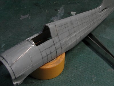
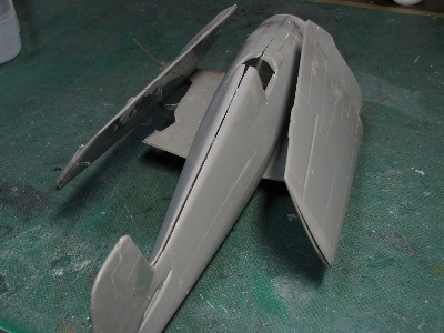
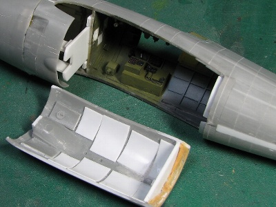
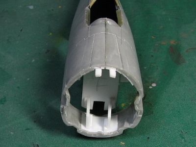
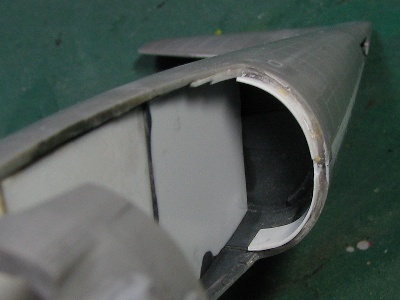
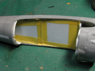
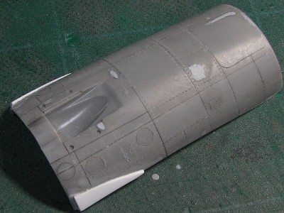
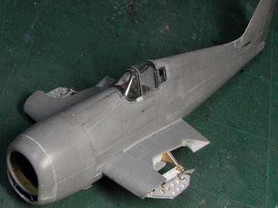
The fuselage of the kit was extended by 3 mm (0.12) using two fuselage parts. The front part was cut on the green line. The back part was cut on the yellow line and then the two parts were joined with CA glue. After the parts were joined, the fuselage section was cut on the blue line and bent. The flat area of the real A/C is wider than the kit. I cut shallowly into the inside of the kit fuselage with a knife and then bent the kit parts to fit the correct cross-sectional shape.
Basically, I use CA glue to attach most of the main parts. I don’t like plastic cement (e.g. Tamiya Cement) as it will sink later. Plaban (styrene sheet) for internal reinforcement is absolutely necessary. because bent parts tend to return to how they once were over time. Plaban maintains the shape I have changed.
Then the fuselage surface was sanded with coarse sandpaper.
The cowling
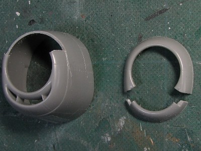
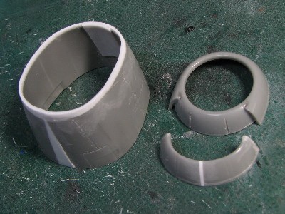
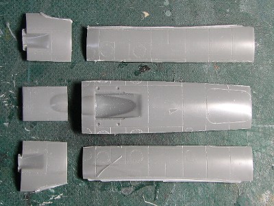
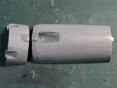
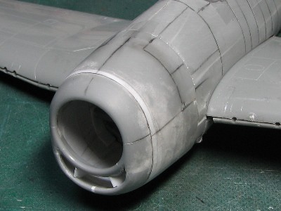
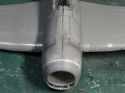
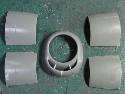
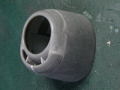
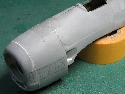
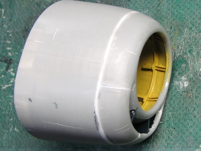
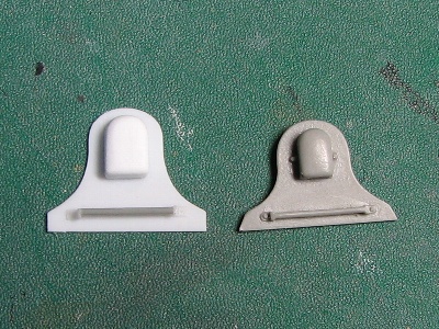
Every kit depicts the “Cat Smile” incorrectly. The reason must be; perception difference. The shape of the upper cover (1) and the upper intake lip (2) are identical and are completely round in the real A/C. But the upper lip (2) and the lower lip (3) have a different shape. The lower lip (3) is slightly wide, low (see the side view drawing below) and is not a true circle. The upper front cover is cut from the cover part of the kit (top right). The upper lip of the oil cooler and the intercooler intake are cut from the other kit (bottom right and left). The upper front cover and the upper intake lip are glued together. The inside is filled with putty. The lower intake lip is widened. The rear cover is enlarged with the cover (white platband). The correct width of the cover is 33.5 mm (1.32″) and the height is 39 mm (1.54″).
The lower fuselage and tail
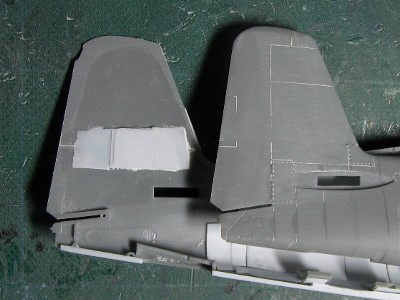
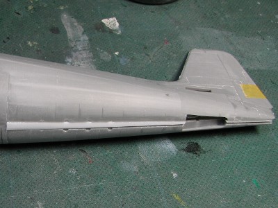
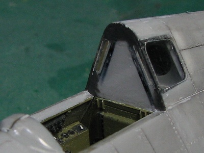
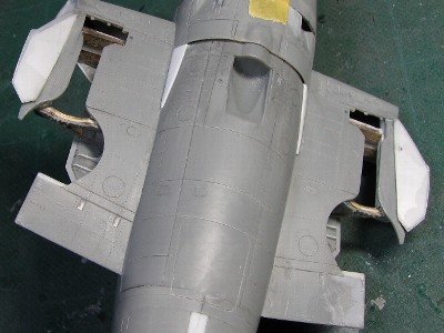
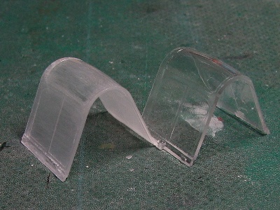
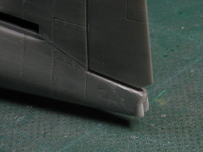
The central part of the lower fuselage is widened using two kits. Each part is glued together. The stem was inserted into the lower fuselage. The tail fin is extended by 2 mm (0.08). The length of the cover is also increased by 1 mm. Thus the cubic volume is significantly increased. The wind shield is Eduard. The is a corrected fuselage and the right is the original Eduard. The Eduard cover is too square and the cross-sectional shape is incorrect.
The second topic is the trick. “Folding wing.”
Calculation for the axis of rotation
The data for the angle of the axis of rotation are written in the drawings from: “Model Airplane News.” However, I do not trust any “secondary documentation” such as drawings, descriptions, illustrations, decals, etc. I may have found inaccuracies in the drawings from “Model Airplane News”.
Therefore, I proceeded to calculate the axis angle with a mathematical approach. See the figures below. The left figure shows the port wing in three-quarter view. The x-axis is along the wingspan, the y-axis is the plane axis, the z-axis is the vertical direction, and the origin is the axis of rotation. See the upper right figure.
Point P moves to Q and point R moves to S with wing folding.
At this time, points P, Q are in plane I, which is perpendicular to the axis of rotation,
and point R & S are likewise in plane II which is perpendicular to the axis.
The position P to Q when the wing is folded becomes an arc and the planes I & II are parallel to each other.
The mathematical formula of a plane is written as (1).
ax + by + cz + d = 0 —-(1)
At this time, a, b and c express the slope of the plane.
And the vector (a, b, c) is perpendicular to the plane.
So when we define the values of a, b and c. we can find the angle of the axis.
Now, let us recall the characteristics of the airplane.
If two planes are parallel, the values of a, b and c in the formula (1) are equivalent to each other and only the value of the intercept term d is different.
Therefore, when we substitute each coordinate of the point P, Q, R & S in the equation (1),
we can get the following simultaneous equations (2) to (5).
a x1 + b y1 + c z1 + d = 0 —-(2)
a x2 + b y2 + c z2 + d = 0 —-(3)
a x3 + b y3 + c z3 + d’ = 0 —-(4)
a x4 + b y4 + c z4 + d’ = 0
is a variable at this time —-( a, b, c, d and d’.
The answer we are looking for is the ratio of a, b, c.
So, at the beginning, we set a = 1.
Then, we eliminate d & d’.
Then finally we get the values of b and c as follows.
b = {(x1-x2)(z3-z4)-(x3-x4)(z1-z2)
c = {(x1-x2)(y3-y4)-(x3-x4)(y1-y2)
The values of the coordinates x1, x2, , , , , z3, z4 can be obtained by actual measurement.
The calculation of b and c is relatively easy when using an Excel sheet. The projection angles of the rotation axis in the zx plane and the zy plane are as follows.
θx=tan-1(a/c)
θy=tan-1(b/c)
So, let’s calculate the actual 1/48th model. The wingspan in the folded position is 65 mm (2.54″) and the height of the wing tip from the upper surface of the wing is about 30 mm (1.2″) in 1/48 scale. The wing’s angle of inclination in the folded position is about 55°, the dihedral is 7.5°. These data were entered into Excel, finally I have a solution that; θx = 28.5° and θy = 26.3°.
In terms of modeling, the projection angle of the main spar plane (θw) is useful.
At the moment, here is the following formula.
tanθw = cosθy * tanθx = a/(b^2+c^2)^0.5
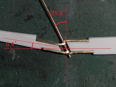
Then θw is 25.9°.
So, I found that the “Model Airplane News” drawings are correct. Was it a waste of time? Yes, it probably was, but I was able to verify that what they drew is accurate and this calculation method can be used not only for the Hellcat, but also for the Wildcat, the Avenger, and even the Fairey Firefly.
The Hinge
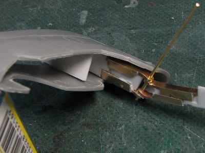
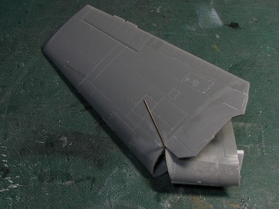
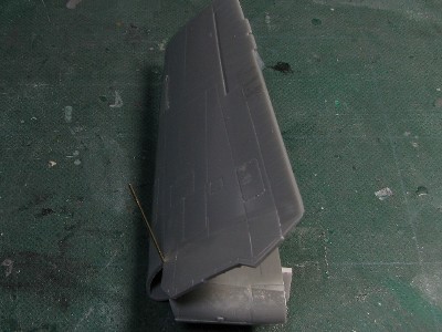
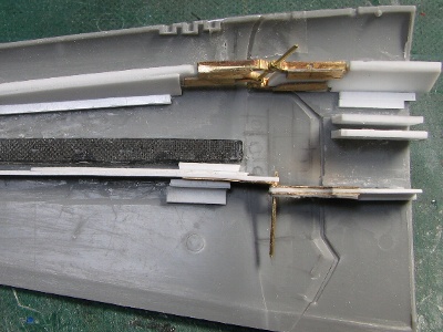
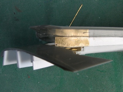
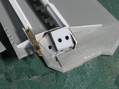
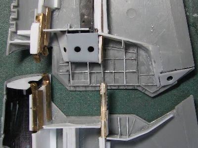
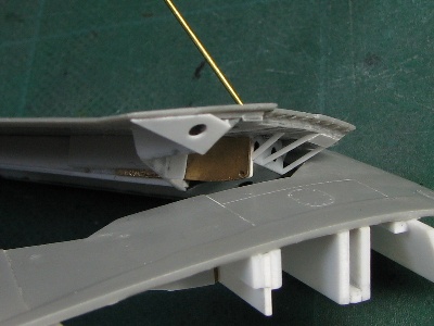
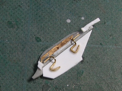
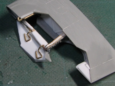
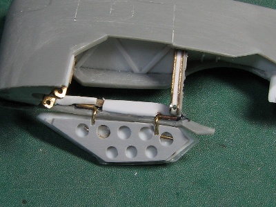
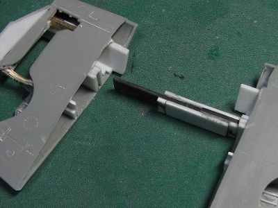
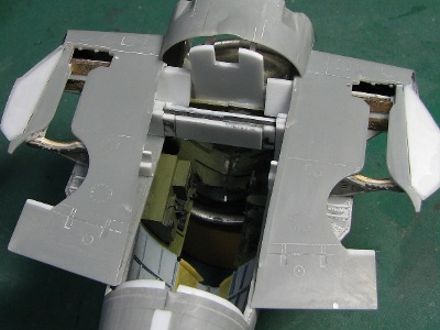
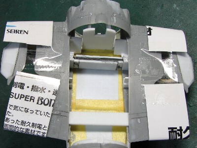
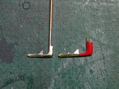
To maintain the accuracy of the hinges, some tricks were needed. Two hinges fit the wing post of the real A/C. If each hinge was separate in the model, accuracy might not be expected. So, I treated the upper and lower hinge pair as one hinge. And the hinge pair and the main body were made as an integral structure.
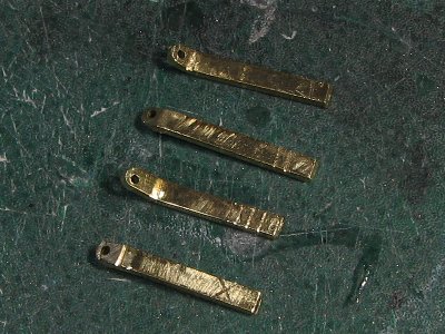
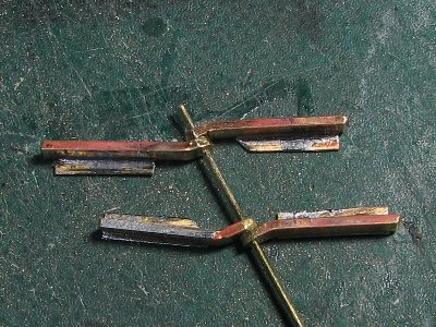
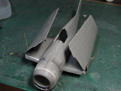
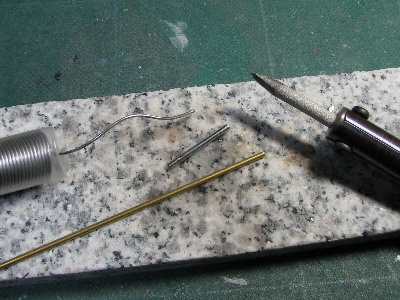
First, the basic hinge structure was assembled. Namely; the brass rod shaft passed through four drilled brass square rods. Essentially, the angle of the brass rod was critical. Then the outer and inner main beams were glued to the brass rods with epoxy glue. This is artifact 1. The main beams made of 1.2 mm (0.05) thick plastic are glued onto the dragonfly. The angle of inclination of the hinge axis is 25.9°. According to my calculations, the projection dihedral of the plane of
Errors (positions or angles of drilled holes, or bent corners, etc.) were released in the adhesion gaps. Namely; Hole position or hole angle errors caused by hand drilling are inevitable. But if the adhesive part between the brass rod and the white plastic rod allows a small gap filled with glue, the accuracy of the hinge alignment is maintained. And if the rod and the rod are tightly glued without a gap, the accuracy of the hinge is not ensured.
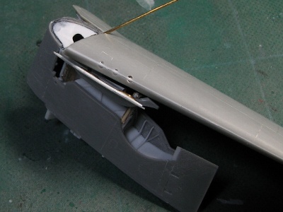
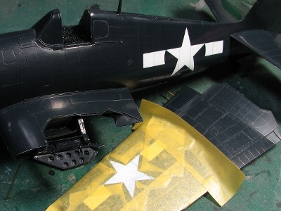
Then, the upper inner and outer flaps were precisely connected with Scotch tape, taking care to maintain the correct dihedral. Then, the completed hinge and rod part was glued to the connected parts of the flaps, paying attention to the angle of the spar web. The bugs were also released in the adhesion gaps. The lower parts of the wing were glued at the end. This is artifact 2. The hinge details were different from the real A/C as you can see, but that is the limitation of 1/48 scale.
The connecting member
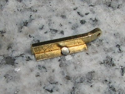
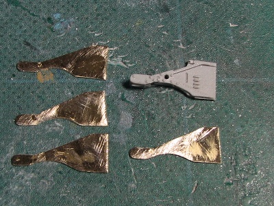
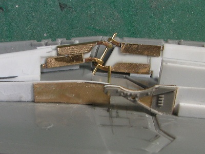
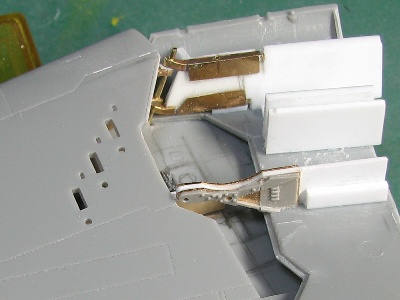
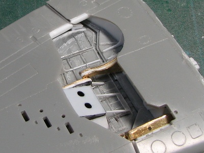
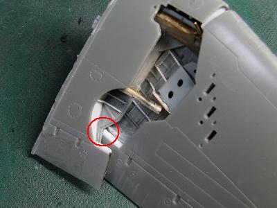
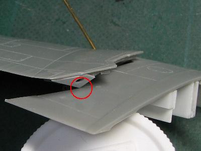
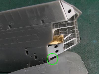
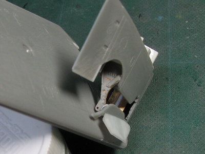
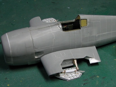
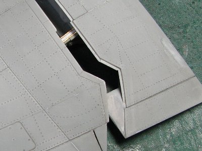
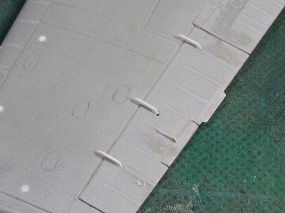
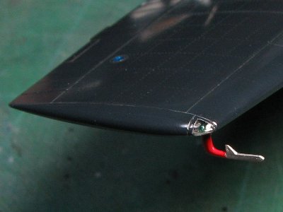
The outer wing of the Hellcat is connected to the inner wing with the pin on the secondary strut. So, I copied these mechanisms in a similar way. I used brass sheet for the connecting member. Each brass member was glued to the inner and outer plastic substrates and drilled the hole for the pin. These subs were connected with a brass pin and glued to the upper parts of the wings. Before construction, I thought it was an easier job compared to the main hinges, but it turned out to be an extremely difficult job. Why was this so difficult? The clearances of these connecting members and the wing cut lines were very sensitive. In other words, the cut lines of the real A/C were designed to clear obstacles with a minimum clearance. However, the size of the connecting member could not be reproduced to the correct scale to achieve sufficient rigidity. Therefore, the connecting members would not clear the wing cut line without fine adjustments in the model. So, the position (high and low, right and left, front and back) of the members and the shape of the cut line were determined after three or four periods of trial and error.
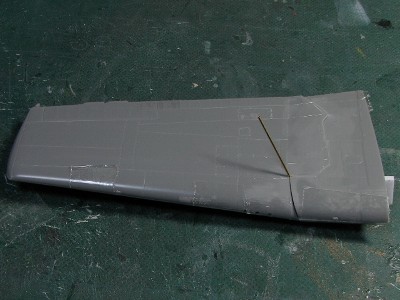
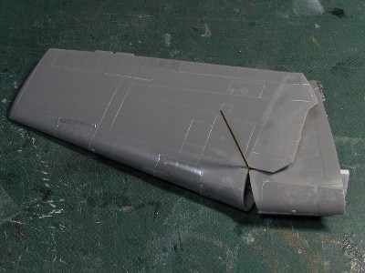
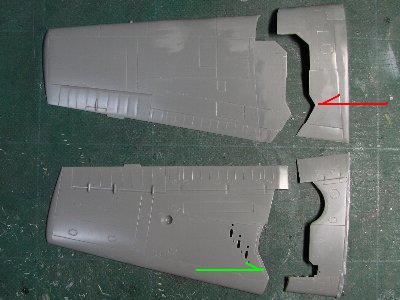
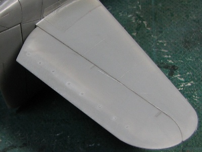
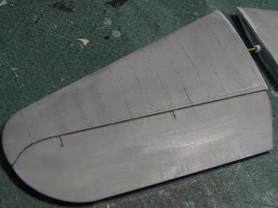
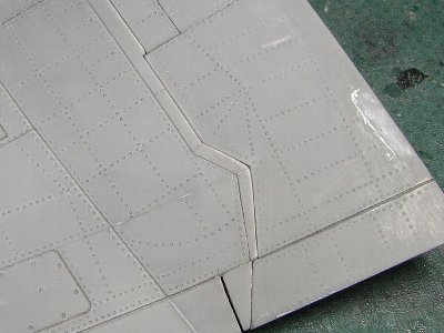
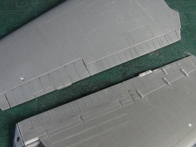
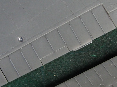
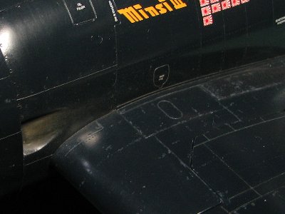
The next problem was the upper parting line. The outer wing turned at very shallow angles (see the photos below). So, the leading edge of the dividing line would have to be very thin, and therefore; it is difficult to replicate the accuracy for a scale model.
Wing specifications
wingspan 42 ft 10 in
wingspan folded 16 ft 2 in
airfoil NACA23000 series
chord ratio (root: center of fuselage) 14.65%
chord ratio (advice: sta.252) 9%
chord (root: center of fuselage) 10 ft 7 in
chord (advice: sta.252) 5 ft 3 in
angle of incidence 0°
washout 0°
dihedral inner wing: 0° outer wing: 7.5°
horizontal flap span 16 ft 6 in
horizontal flap angle of incidence 1.5°
excluding vertical fin set 0°
tail fin thickness ratio 11%
The fuselage continued
The hood again
I was not satisfied with the previous corrected cover. So, I bought another kit (three kits in total now!) and started the cover again. The front section was reused. The new side of the cover was divided into four pieces and rejoined with four fins. The width of the upper stem was 2 mm (0.08) in front and 1.5 mm (0.06) in back. The side stem was 0.5 mm (0.02) in front 1 mm (0.04) in back, the lower stem was 2 mm (0.08) in front 2.5 mm (0.1) in back. It is finished. The outer perimeter of the end of the cover is enlarged by 6 mm! (0.24) in total.
The cockpit
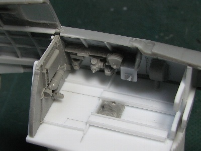
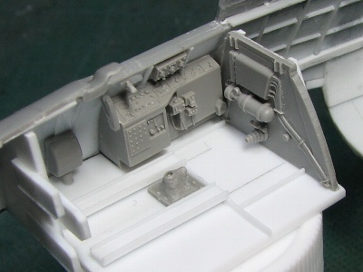
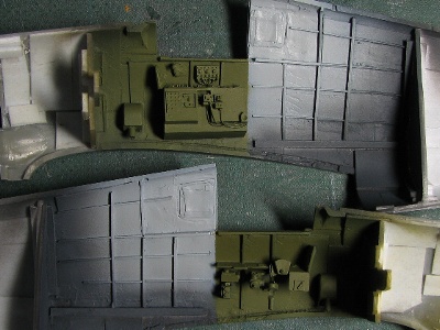
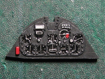
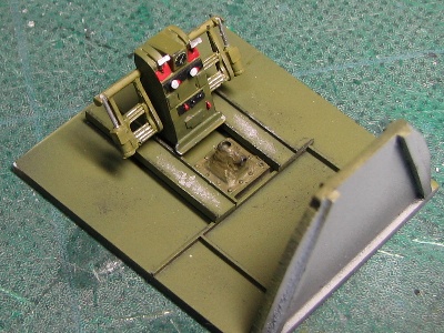
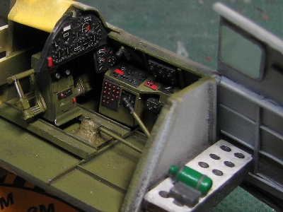
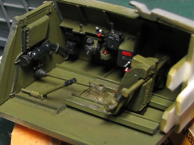
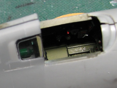
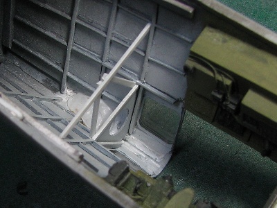
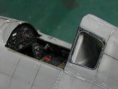
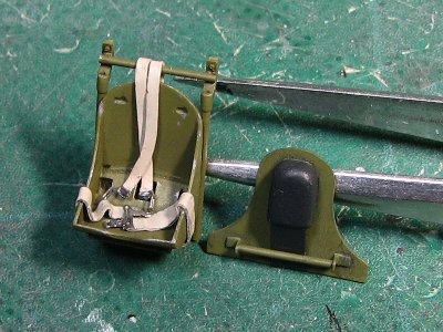
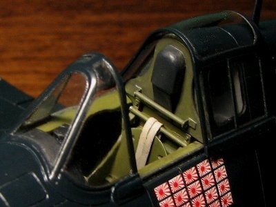
The cockpit is painted green on the inside. The rear fuselage is light gray. I didn’t know the exact color, but I used the main color FS-36495.
Bonding fuselage parts
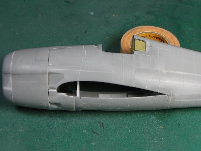
The fuselage parts were previously stretched and bent to correct the external appearance of the Hellcat, so the left and right parts were not exactly mirror images of each other. So, any errors in the bonding process can cause distortion. At first, I glued the upper rear fuselage with plastic cement. Then, after careful inspection for distortion and when no distortion was found, the nose and tail fin were glued with CA glue.
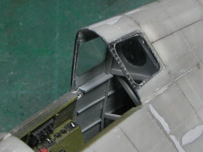
After that, the fuselage shape was brushed. The surfaces of the hood and front fuselage are joined not smoothly but in dashed lines as I described in the side view and in my drawings.
The engine and cowling
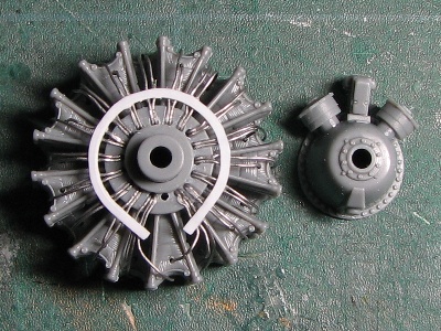
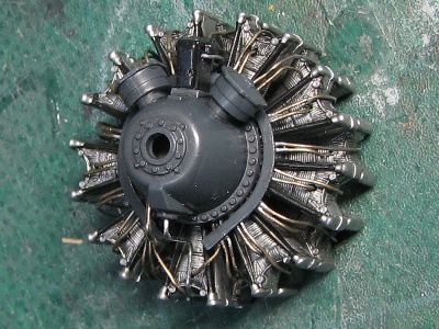
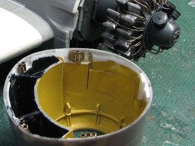
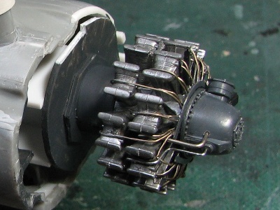
The inside of the F6F-5 cowling is painted in yellow zinc chromate. This makes the details easy to see. The Double Wasp R-2800-10W engine is from the Tamiya P-47. The Tamiya Double Wasp has very good detail, but a little smaller in diameter.
The gear bay
The wing again
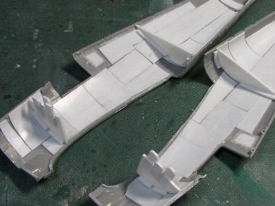
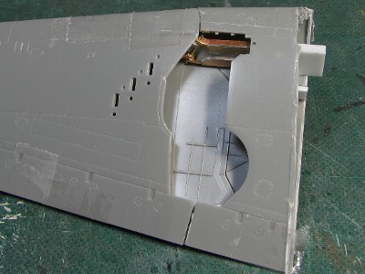
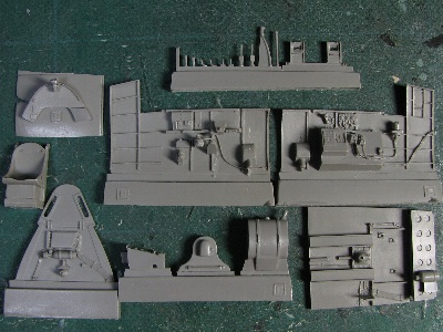
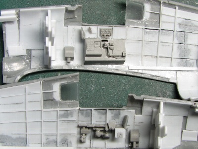
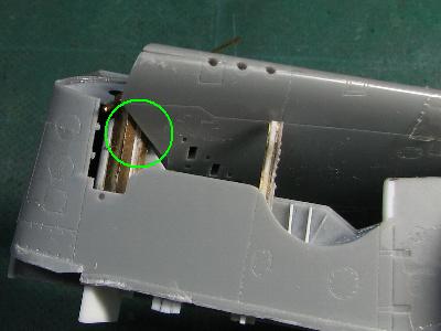
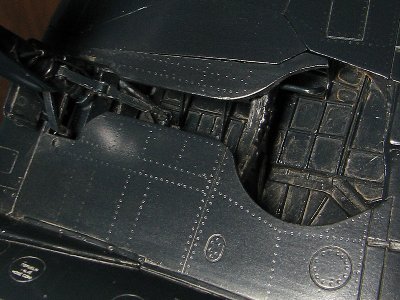
The next topic is the Main Landing Gear bay. I bought the Aires resin tool detail kit but couldn’t use it because of the folding wings. The details had to be completely built.
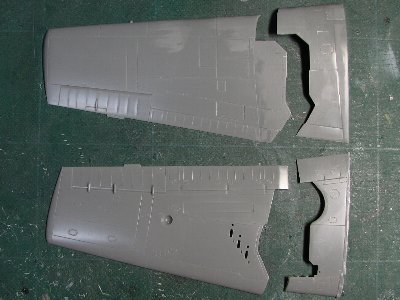
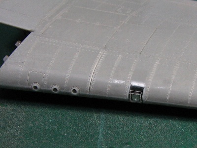
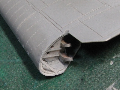
Unfortunately, I couldn’t depict it completely like the real A/C. Reasons? (1) there is the wing parting line in the center of the gear position, (2) the position of the connecting member is not correct. interfered with the wing cutting line, (3) the wing cutting line and the kit opening shape were a bit wrong, (4) the thickness of the gear case roof could not be thinned for riveting work.
By the way? This wing cutting line is complicated, but when the wing moves we can understand the necessity of every angle and line.
As the gear case was finished, the top and bottom of the wing were glued together. As already mentioned, the absolute thickness of the central wing area is fixed in the real aircraft. So, the wedge-shaped rim was inserted into the leading edge glue line to increase the thickness to 0.5 mm (0.02) at the wing folding line.
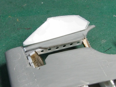
The lower small door
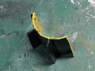
There is a small door on the outer side of the gear compartment. The purpose of this door is to prevent the outer and inner wings from interfering when the wing is folded.
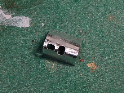
At first, I drew a rough sketch. The orange figure is the door, the gray is a fixed part, and the hinge is the combination of a blue tube and a green rod. In this kind of hinge door, when point A is moved to A’ and point B to B’, the vertex of the perpendicular bisector of the straight line segment AA’ and the perpendicular bisector of BB’ becomes the axis of this hinge (A and B are arbitrary).
Then I started the construction. And also, I found that the construction of this door was very difficult as was the connecting member of the wing. As you can see in the sketch, the axis is a little inward from the cut line. Therefore, the green rod has to be bent to clear the edge. However, the thickness of the bent rod is limited while the wing is folding.
Inside the door is a perforated plate. I cut this plate from 0.14mm (0.006) plastic sheet with my home cutting machine “Craft Robo CC330-20” and I punched the mechanism for the door in the closed position. But, the door can be fixed by the friction between the tube and the rod. So I left it rough.
The horizontal stabilizer
Examining the horizontal stabilizer
The part of the kit is not too bad. So, intermediate modelers can build it straight out of the box, however, it is not perfect. The maximum thickness point is at 30% of the chord in the kit, but it is halfway back on the actual A/C (see my drawing). The airfoil is close to a laminar flow airfoil and is aimed at high efficiency in high speed flight. The airfoil is the same as the vertical fin.
It is assumed that the left and right horizontal stabilizers are interchangeable, but if you look closely, you can see that the upper and lower fuselage connection lines are different. I think most parts of the fin are interchangeable, but the panel where the connection line is located is different.
While checking photos of the existing A/C, I noticed that some aircraft have the panel line that is not described in the existing drawings along the leading edge. But some aircraft may not have this panel line, judging from the photos. I think there are three possibilities. Some photos may not show the panel line, but all air conditioners have the line. There are actually two types of real A/C (those with, those without). This panel line is added during restoration or repair. I don’t know what the correct answer is, but it could probably be
Fuselage Panel Rivets and Lines
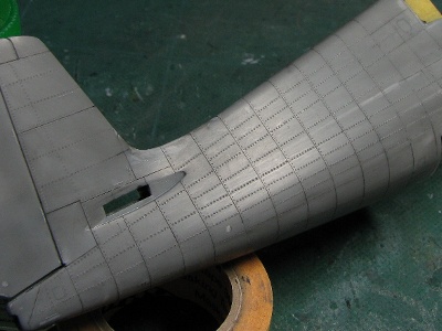
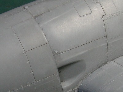
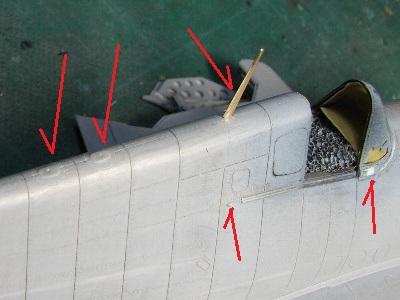
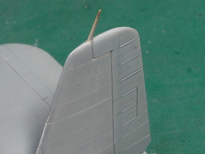
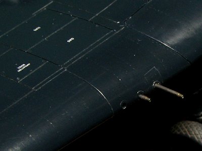
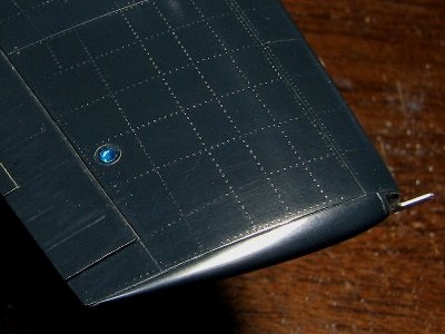
The Hellcat has convex (raised) rivets on the rear fuselage (after panel #3, to be exact) and flat (recessed) rivets on the other surfaces (the main wing, tail fins, and forward fuselage). But I couldn’t picture any truly convex rivets. I used #1 (0.3mm = 0.01″) ball nose tool for convex rivets and #0 (0.25mm) for flat rivets. #3 to #5 are used for fasteners. They were chosen by the situation. #5 was for the cover, #3 or #4 was for the small access panel.
There may be a slight difference in the string arrangement on some A/C (early model -3 ?). But I couldn’t figure it out yet. Anyway, I tried to depict the normal -5 arrangement.
Rivets and wing panel lines
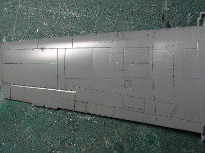
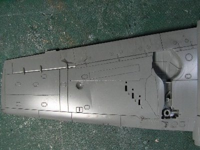
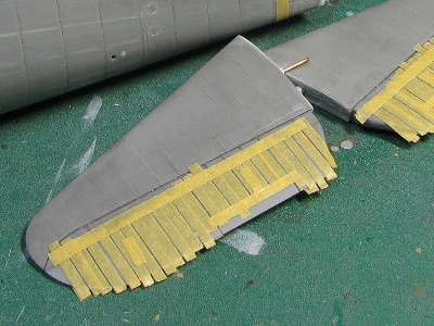
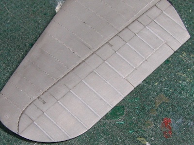
The panel lines of the -5 wings are quite different from the -3 (especially on the upper side), but the Hasegawa kit depicts a -3 wing and, the kit has a few mistakes. So some extra work is needed to correct it on the -5 wing.
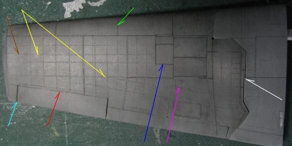
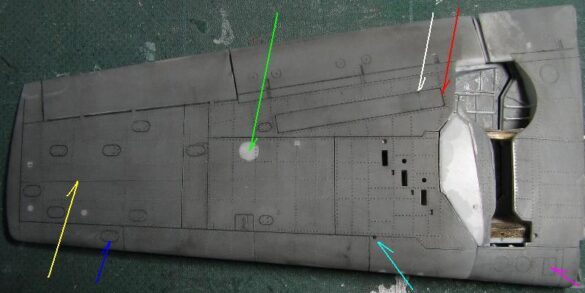
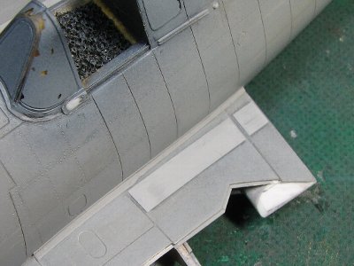
Neither the panel lines nor rivet lines in the existing drawings are not correct. I checked the wing station number and the actual A/C photos and then figured out the correct panel and rivet lines as much as possible. See the photos of my model below. Below are some observations.
The panel lines are compatible with the existing restored A/C. I deleted some panel lines that could not be seen on the restored A/C from the existing drawing.
The panel line located on the upper strut flange is exactly 90 degrees to the centerline of the fuselage. Thus, the panel line on the lower flange has a slight sweep back for the taper of the oblique strut.
Some existing drawings show ribs on the front of the main wing being bent outward, but I could not confirm this.
The inner wing is covered with metal skin so that there are rivets as well.
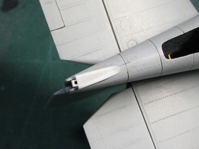
The trailing edge of the fixed wing needs to be moved back 1 to 2 mm (0.04 – .08 ) (red). The plane’s span is enlarged 1mm (aqua). The panel line is on this rib (same as the -3 model) (green). Some existing drawings show panel lines on these chords, but they are not confirmed on the actual A/C (yellow). This panel line is moved forward 1 mm (blue). The kit access panel interferes with the rivet line, so this panel is reduced (magenta). This wing parting line is straight and has no crank on the actual A/C. Well, I know I didn’t fix it (white). Only this side is bent at this point and reaches the wing side (brown). The long access panel of the box in front of the wing on the underside is better if it is enlarged by 5 mm (0.2) towards the fuselage (white -> red). The port landing light hole should be filled. Only the -3 model has this type of light (green). This panel line is not confirmed on the -5 model (does the -3 model have it?) (yellow). Here a small ellipsoidal access panel is added and the positions of the other panels are adjusted (blue). This square access panel is only the port (magenta). This small hole is for connecting the outer wing with a pin on the folding (aqua). Basically, the port and the right wing are identical unless a special note is added.
The windscreen and canopy
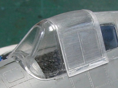
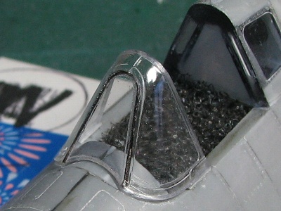
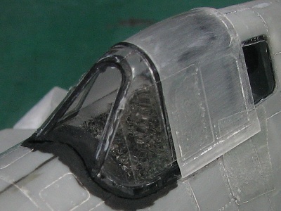
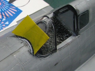
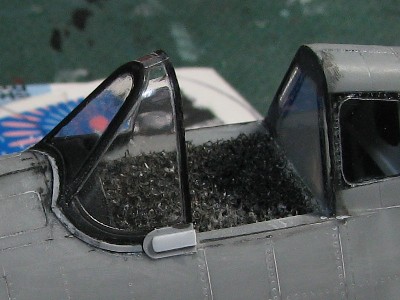
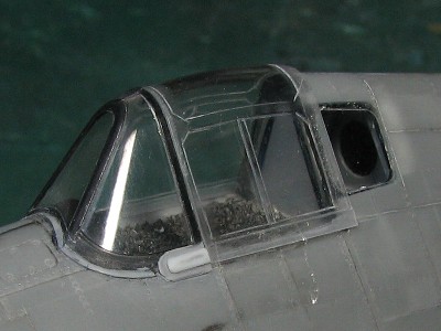
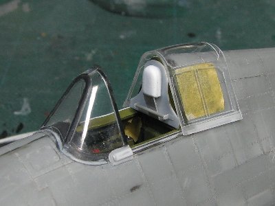
I used the Eduard windshield and canopy parts because they are basically well-shaped. I intended to make the canopy slide and close. In order for the canopy to slide. the rear edge of the canopy section needs to be sanded very thin.
The tire
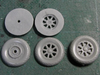
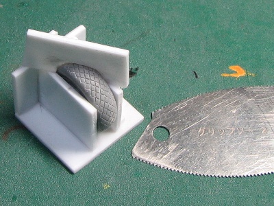
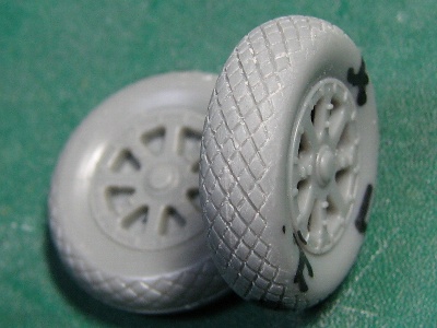
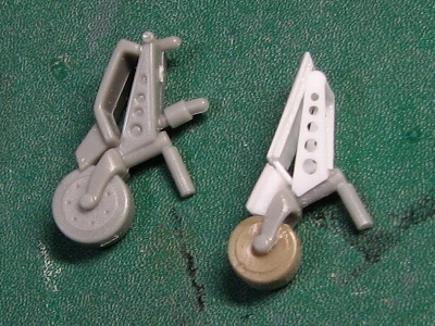
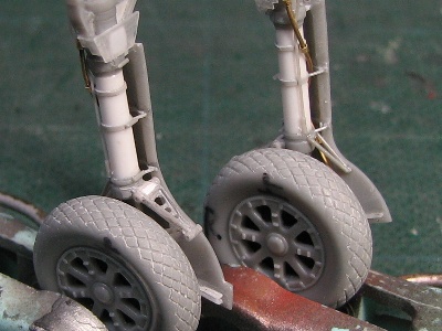
The tough look of the Hellcat is undermined by the thin Hasegawa tire kit. So I increased their width using two sets of wheels. The diamond tread is carved with a thick carving saw and this jigsaw.
The landing gear
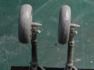
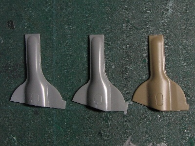
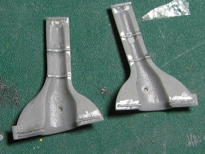
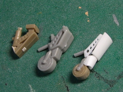
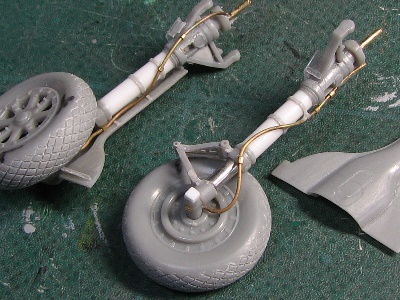
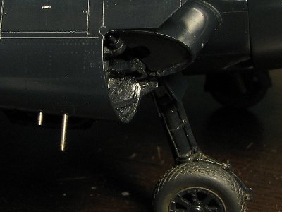
It is not often known that; there are two variations of the Hellcat landing gear doors. The kit part can be used up to the early -3 model. It is confirmed on the -3 model with a small blister on the side of the cover. After the mid-term of -3, the bottom is cut off and this type is used through the last Hellcat. The Hasegawa part is well modeled in itself. unfortunately, the position relative to the foot is wrong. the cover is too low. And the Edward cover. has the wrong shape.
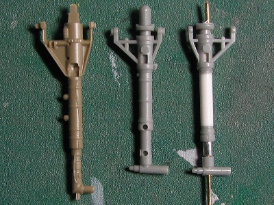
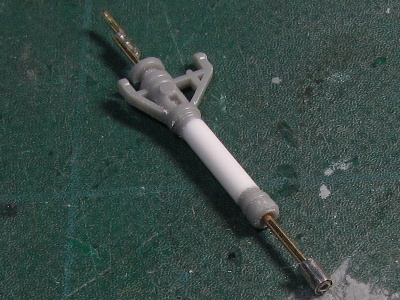
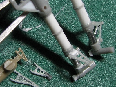
The torque joint is important for Hellcat modeling and is very visible. Engraving parts are convenient, but poor in 3-D. So I scratch built them from 0.2mm (0.008) plaban with their “H” cross-section. Details such as the number of holes and the shape differ between t
Propeller
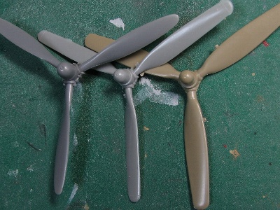
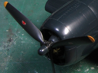
The kit part is not bad, but the spinner is too small and the blade is a bit narrow. This is unfortunately a Hasegawa characteristic. The easiest way to fix this is to use a Tamiya F4U-1D part, but I didn’t have any. So I chose an Accurate Miniature SB2C-1 for the center and Tamiya P-47D for the Hamilton paddle blades from my junk box. The Tamiya blade is well-shaped. So I just sanded it to thin it out. This corrected (widened and reshaped) propeller depicts the high power and performance of the Hellcat much better!
Control Surface Fins
The fins are depicted with a surface arrangement as usual. The fixed blade is aluminum foil.
Paint & Marking
And then, sufficient and necessary surface material was lightly sprayed to prepare it for paint.
Historical Research
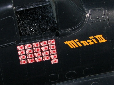
I chose the “Minsi III” BuNo 70143 of the Navy’s top ace, Commander David McCampbell. who was the commander of Carrier Air Group 15 on the USS Essex. Be careful. some existing decals and marking guide images are incorrect. Photos of the actual A/C are available from various references, although all are on the right side.
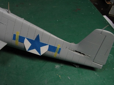
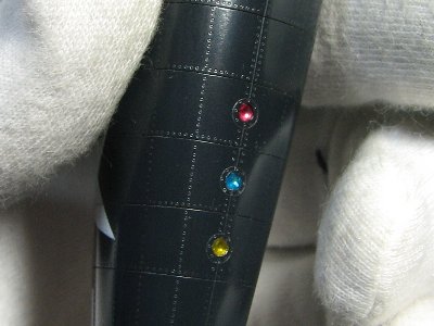
The “Minsi III” lettering, size, position and color and details of the scores are confirmed by reference photos. So I basically traced the actual photo of the “Minsi III” logo. However, the original shape of the “III” is not clever in design, so I corrected it in my model. See the letter shown below. The number of scores is confirmed by photos as 19, 21, 30 and 34. I show each condition with white, aqua, yellow and pink in the drawing below.
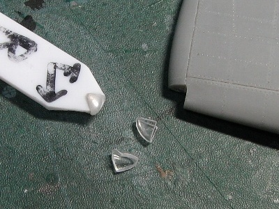
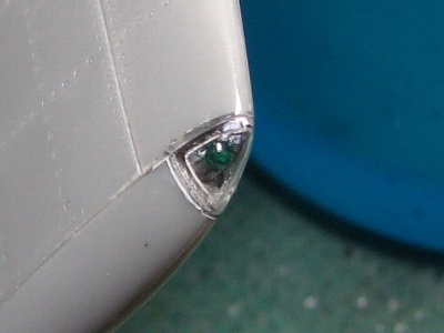
There is a 5 inch wide white stripe on the top of the tail fin. As for the Minsi II, the small letter “CAG” is written in the white band. How is it Minsi III? the photo is not clear, so I can’t confirm. I don’t think there are any letters. And, the Aeromaster Decal includes the letters “CAG” on the small square gear cover, but there is no photo to prove this. I guess AMD may have assumed it was there looking at the Minsi II.
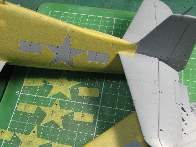
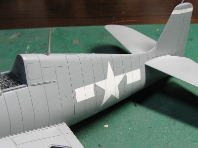
The sea blue for wheels is confirmed by the photo. The spinner and propeller hub are painted dark. I painted the spinner Glossy sea blue, but there is no confirmation. The fuselage insignia is 50 inches (the size is shown by the inscribed circle of the star) and the wing is 45 inches. The fuselage insignia is painted perpendicular to the fuselage frame line on the actual fuselage surface. So, it looks slightly tilted to the fuselage reference line in the side view drawing. (i.e. The white insignia bar and the red fuselage reference line are not parallel in the drawing above.) While the fuselage panel line is exactly perpendicular to the reference. line in the side view. SO WHY? Well, it can be understood while thinking in 3D.
Glossy sea blue is a mixture of Mr. Color #365 Gloss Sea Blue with 20% Black plus a small amount of red. I don’t like the greenish blue of #365. Then, a small amount of flat base is added to aim for 1/4 satin flat.
The surface of the orange peel and the step on the white/blue outline were polished with Mr. Laplos #6000. Then the base paint was completed.
Completion
After almost a year of construction, the Hellcat is finally completed.
As for the trick of folding the wings, I am not completely satisfied with the accuracy for this scale model. Although with the rigidity, accuracy and smooth movement of the folding mechanism I am completely satisfied. This is the result of using metal hinges and the pin connecting the pieces.
As for the main topic? “complete reproduction of the true contour of the Hellcat,” I am 100% satisfied. The wide and bulky hood, the evil cat smile, the sharp wind shield and dome, etc. I fall in love with her all over again.
F6F-3 Κ & F6F-5 Κ Hellcat Drones

