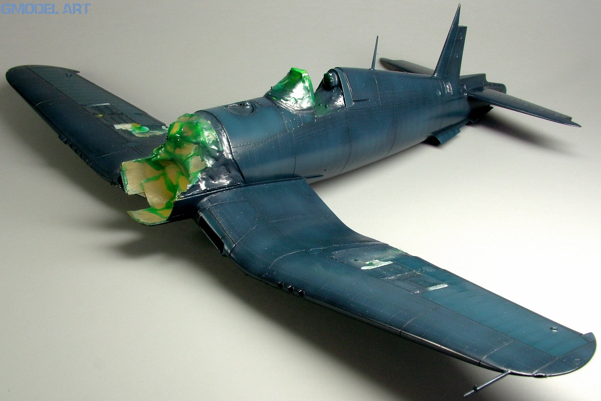
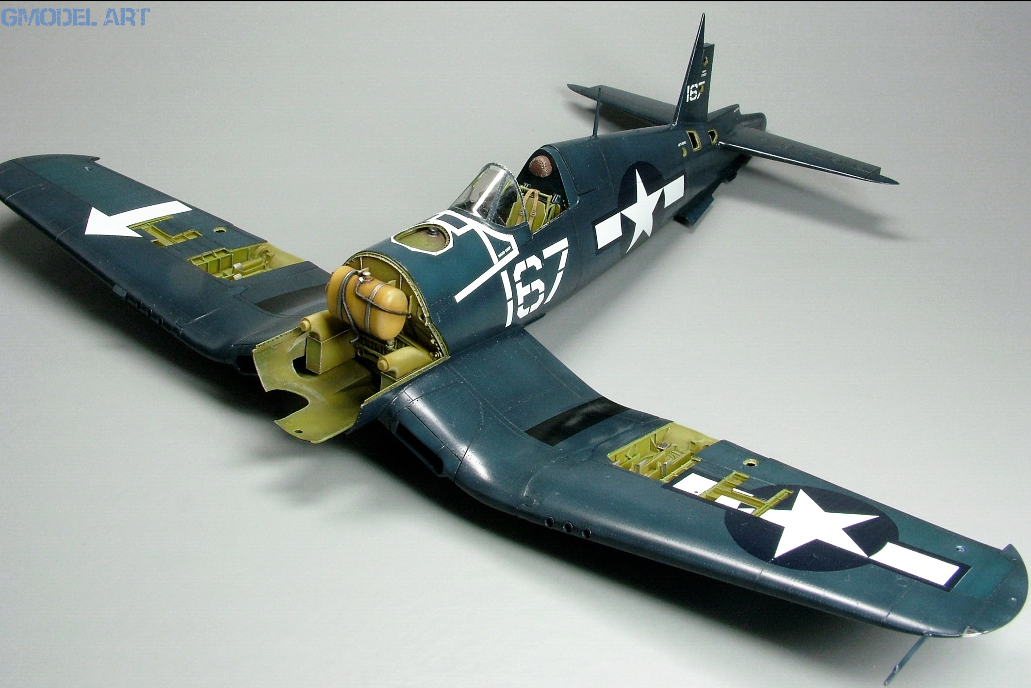
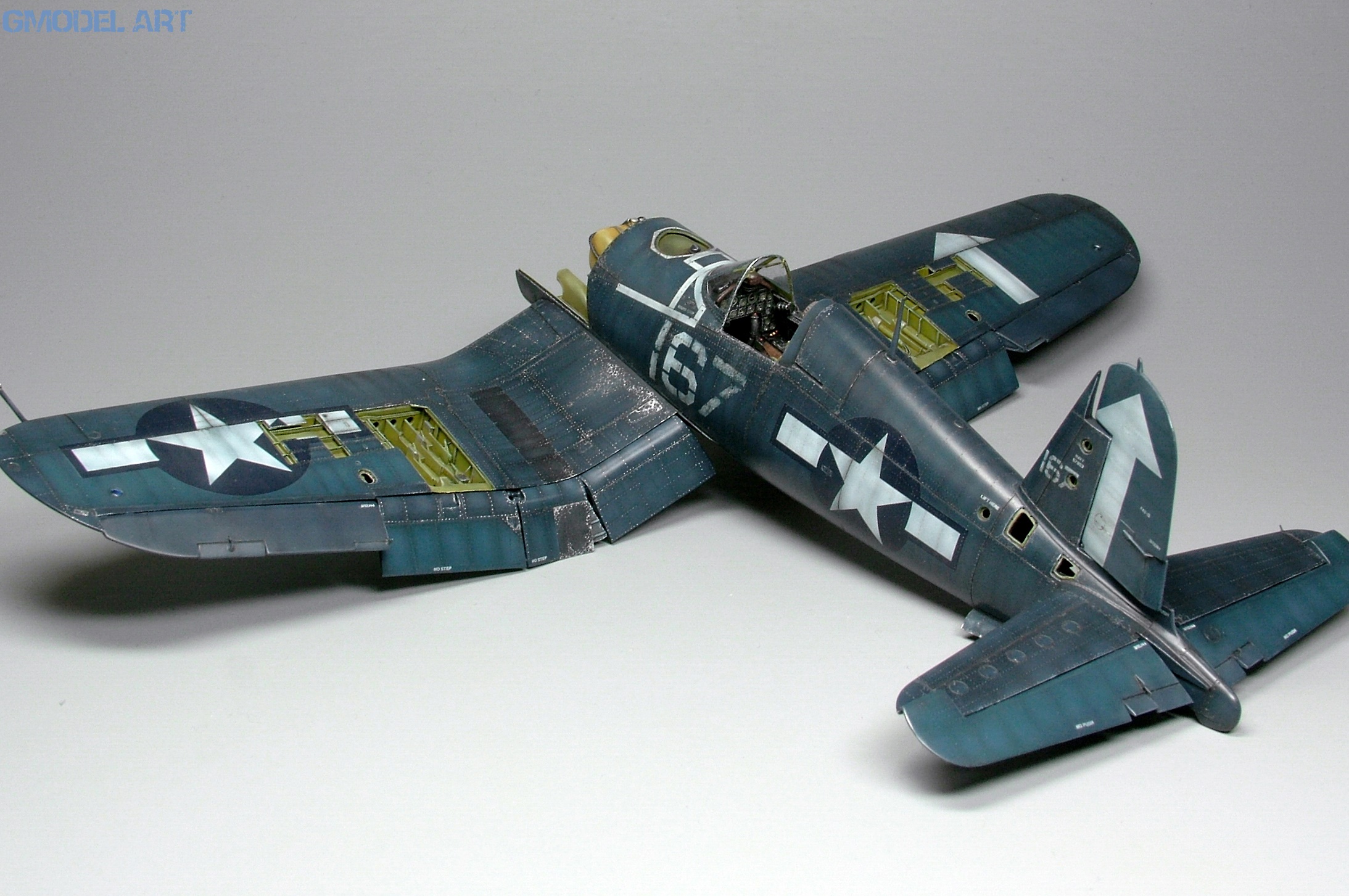
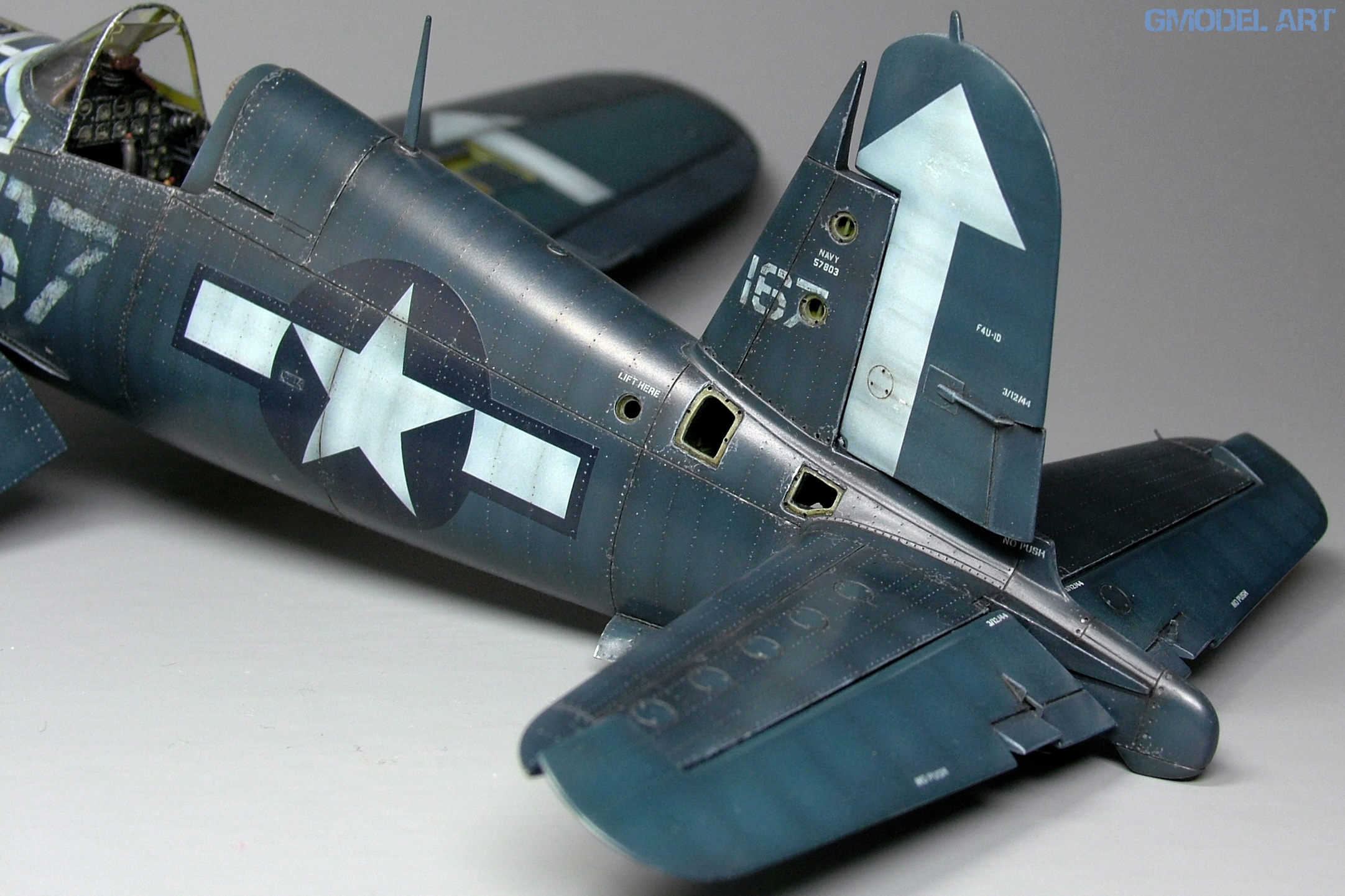
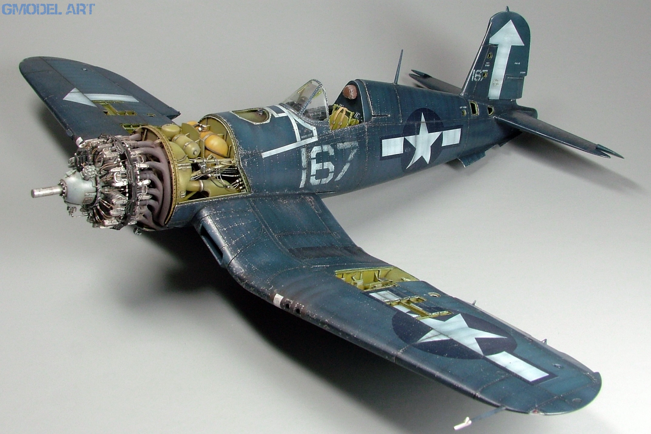
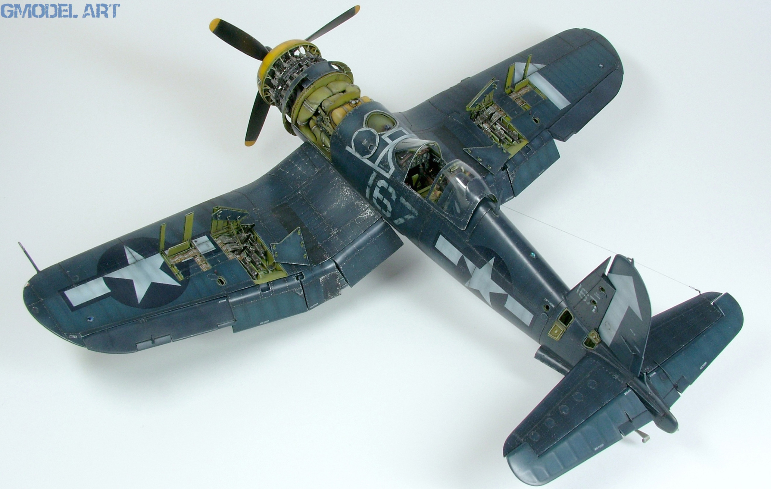
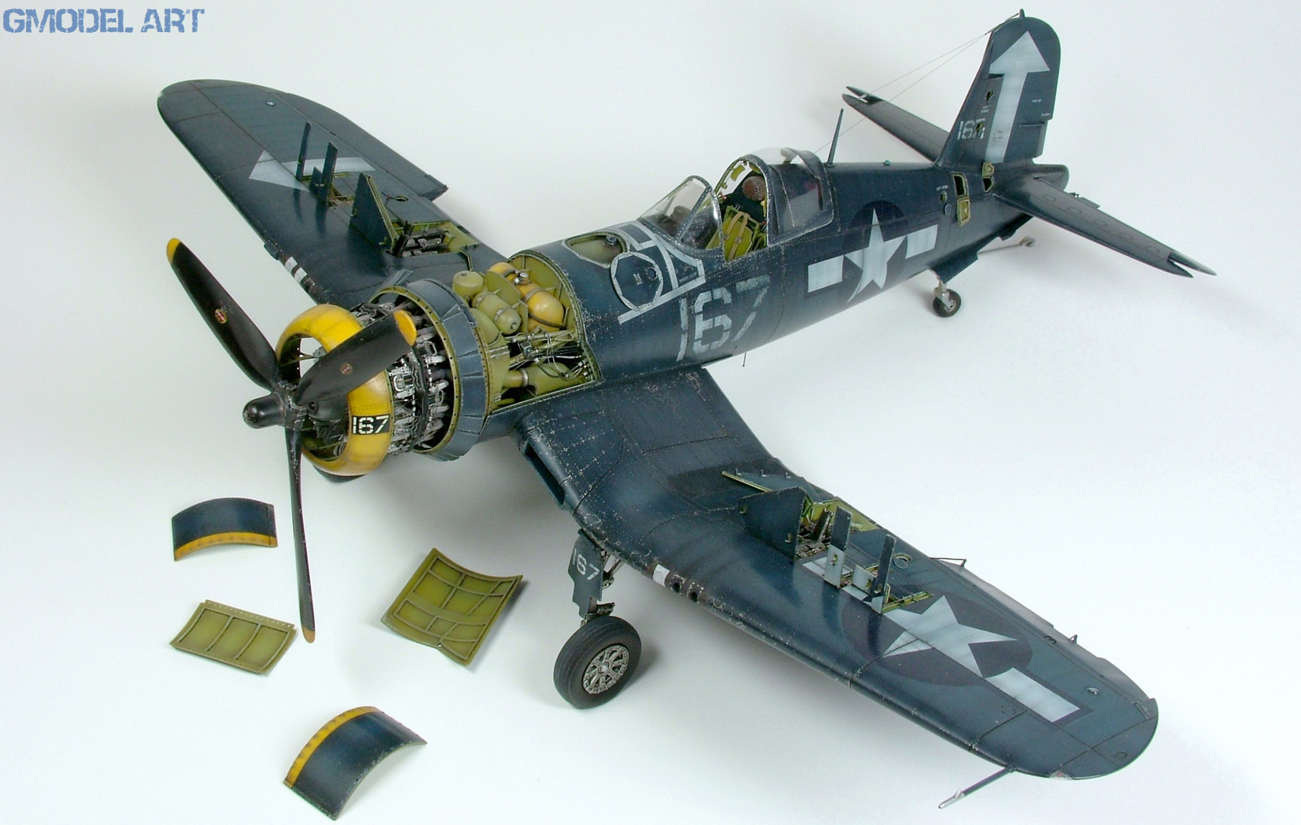
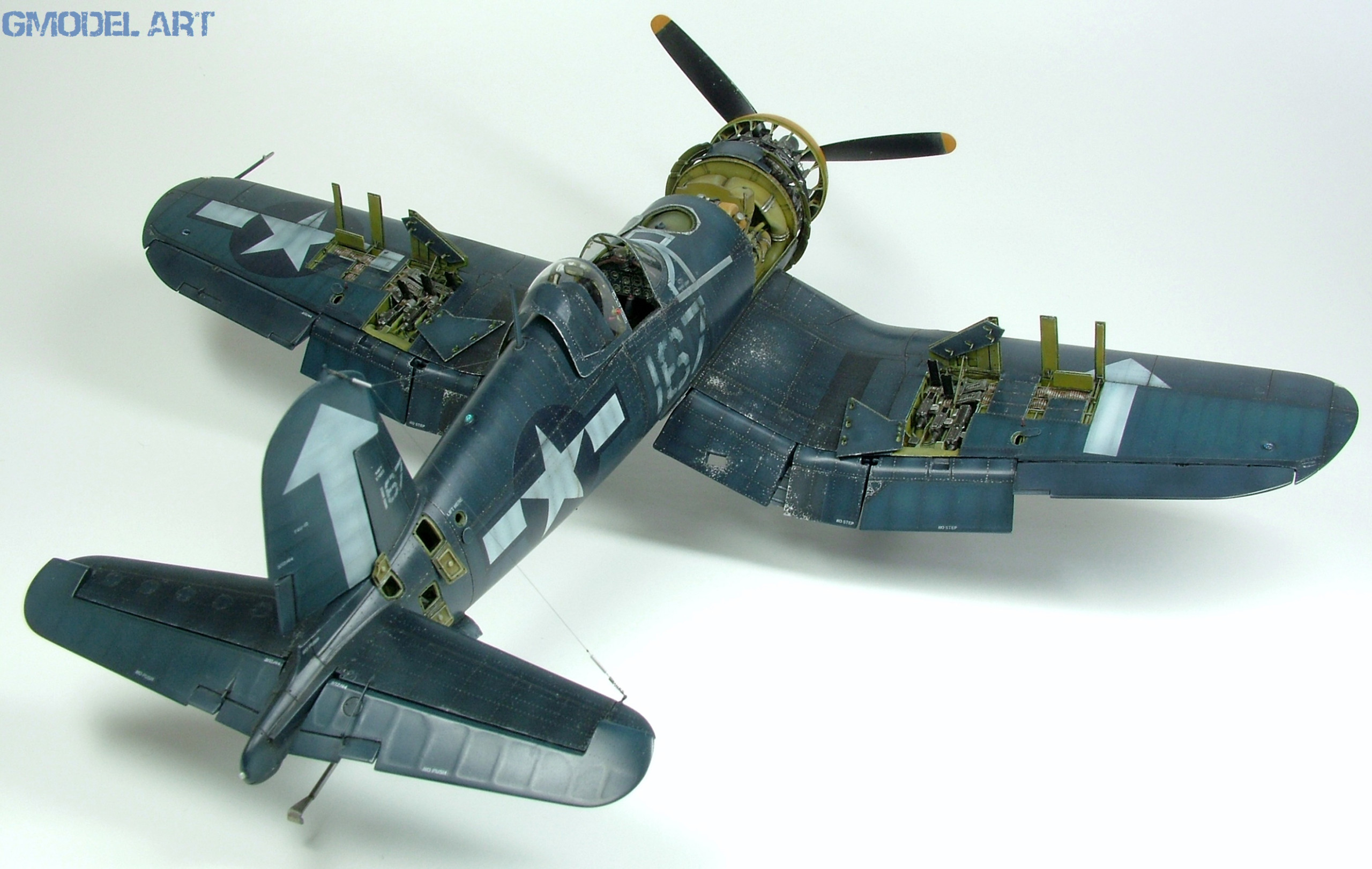
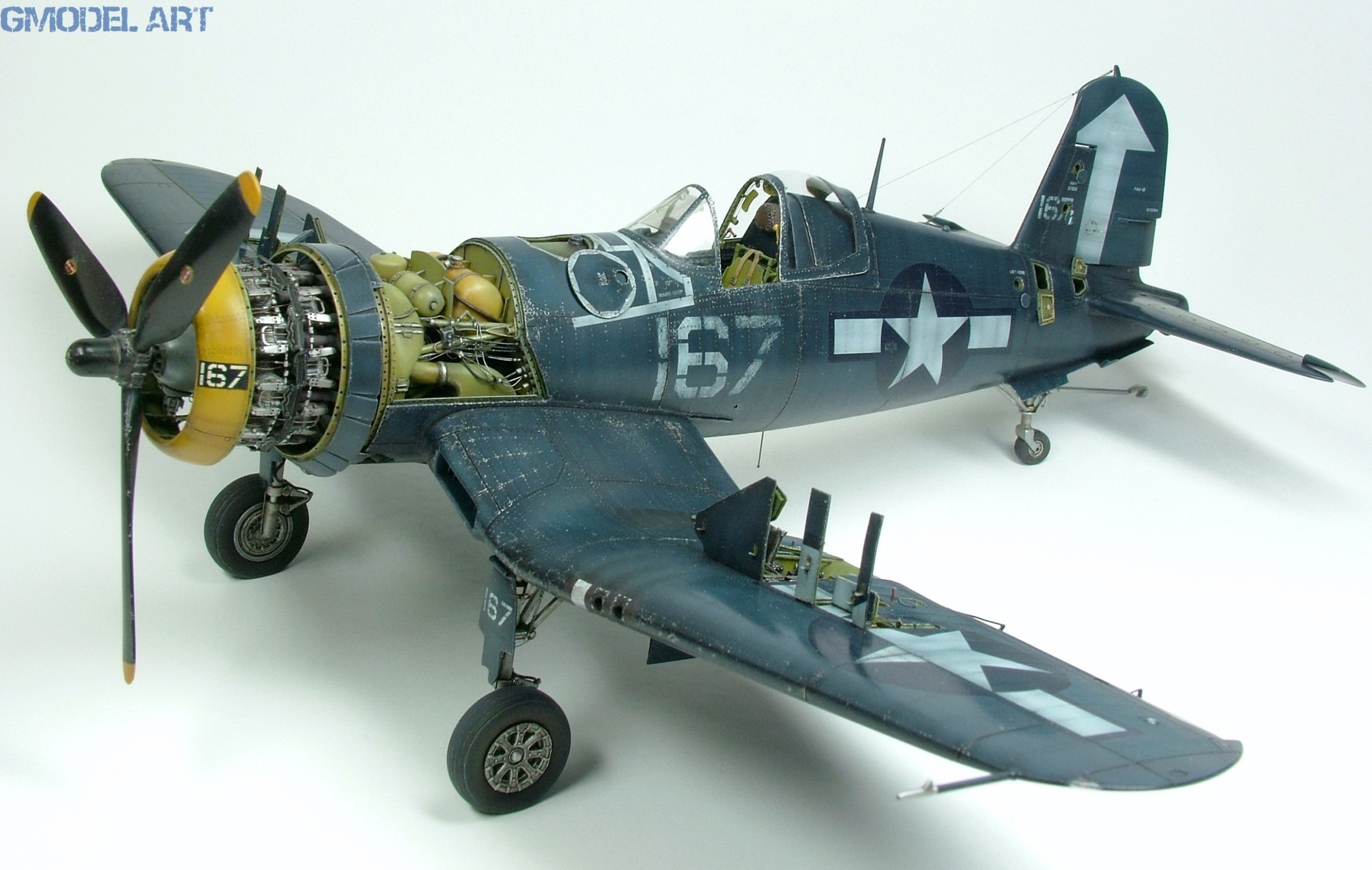
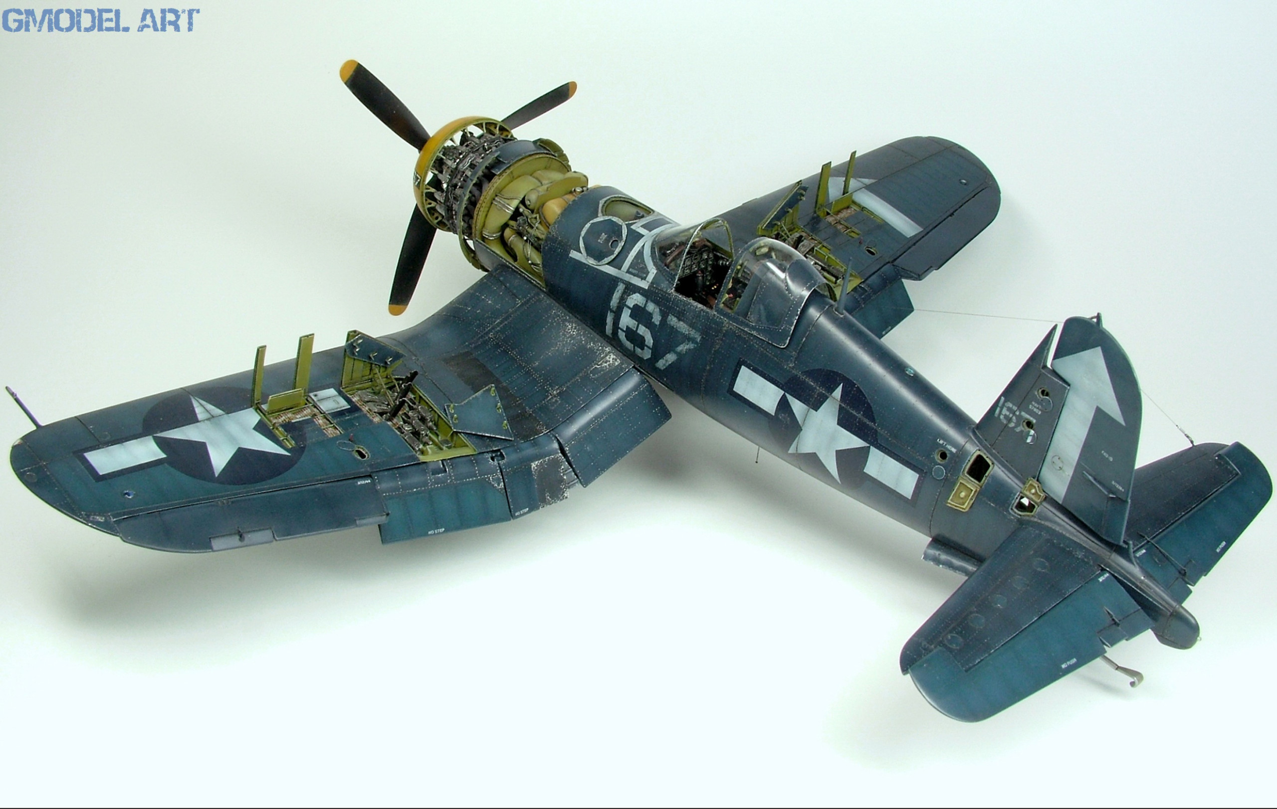
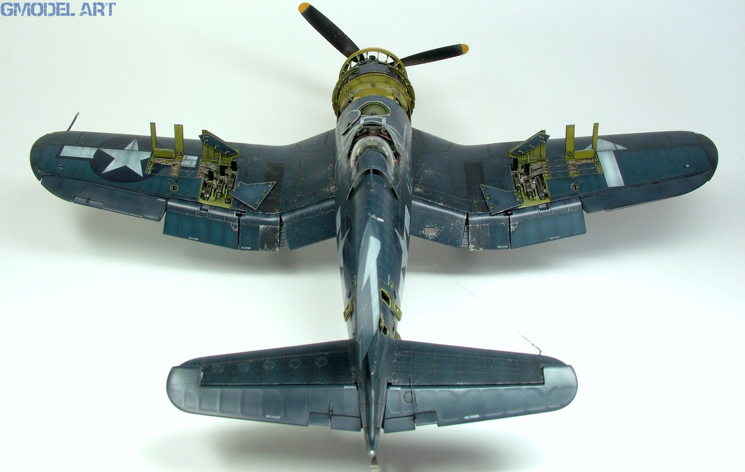
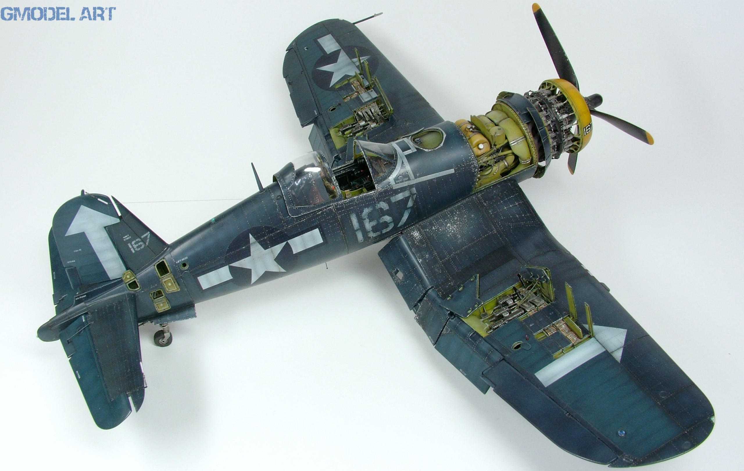
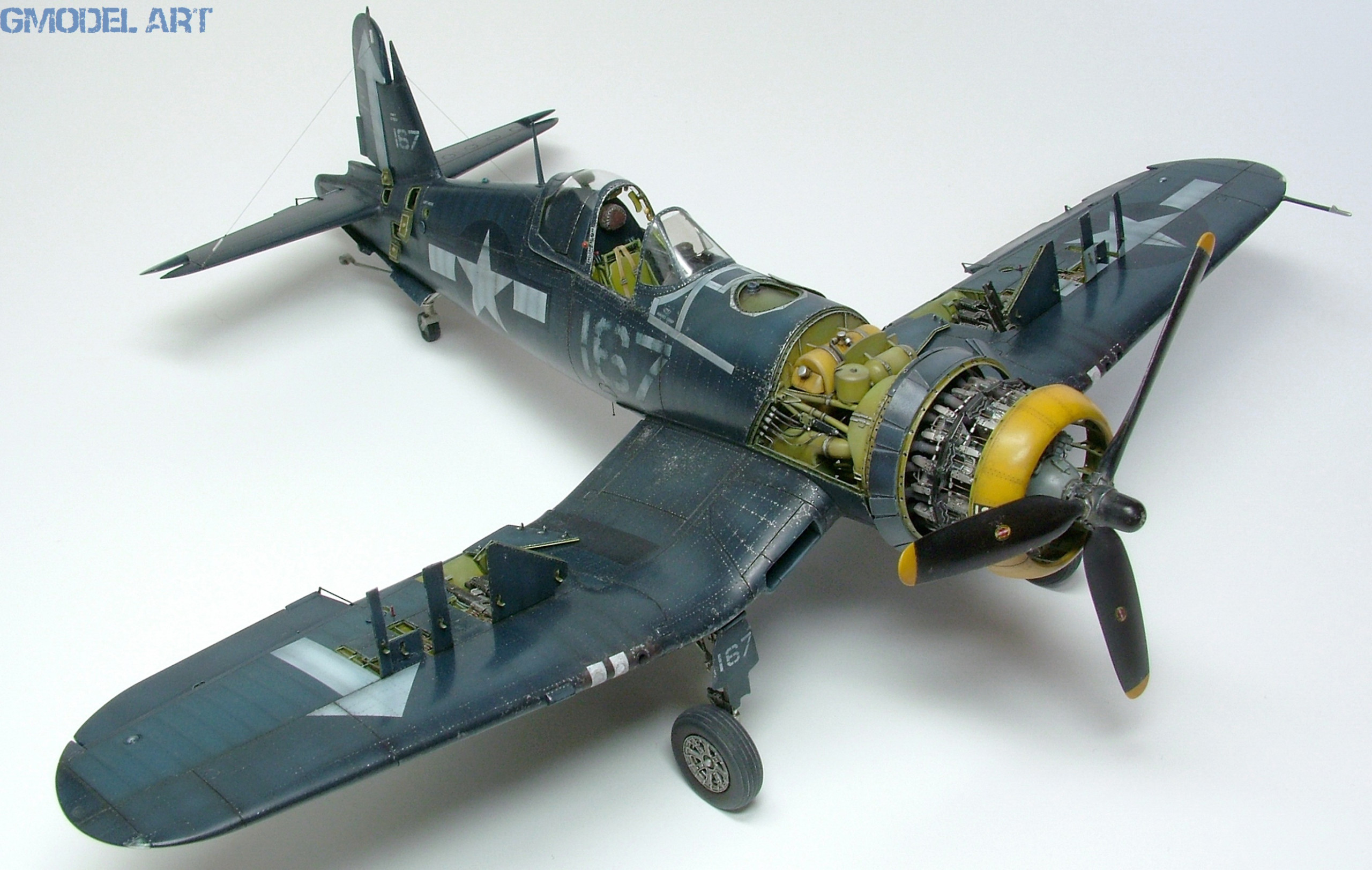
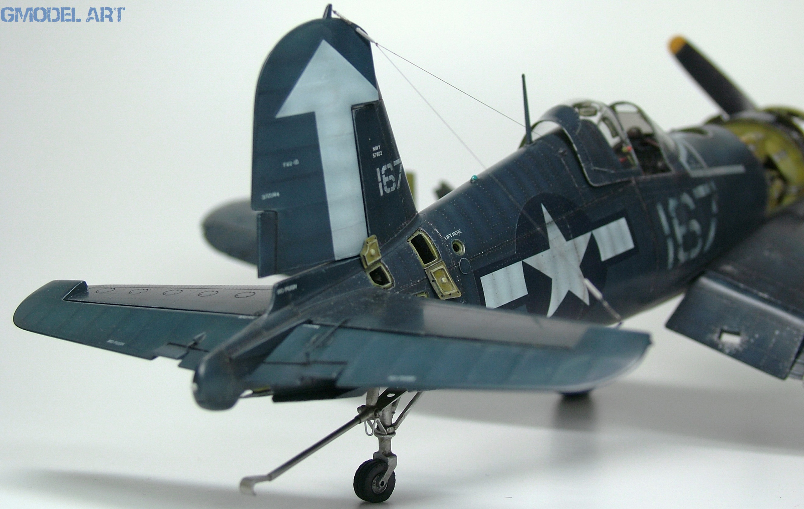
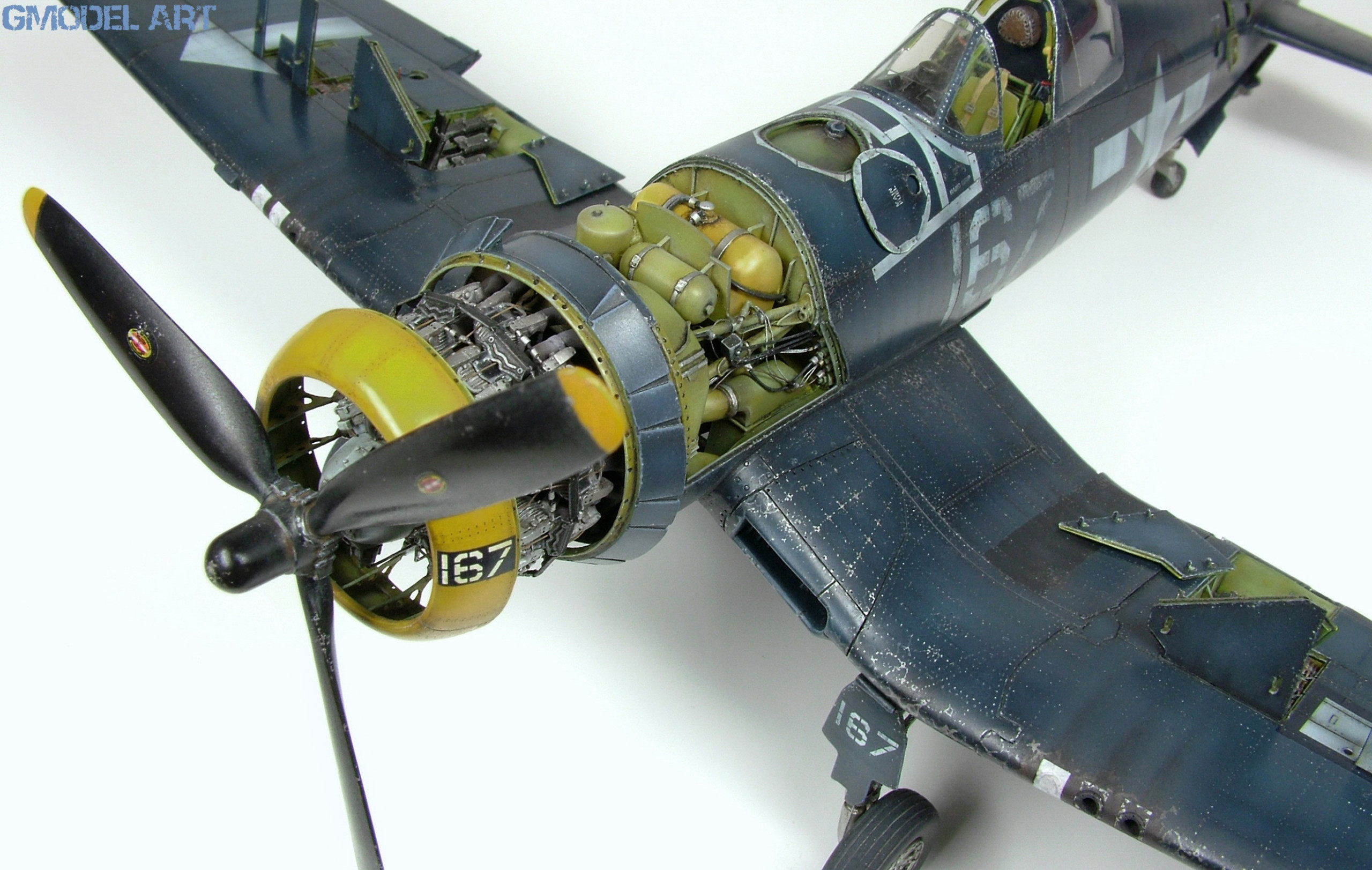
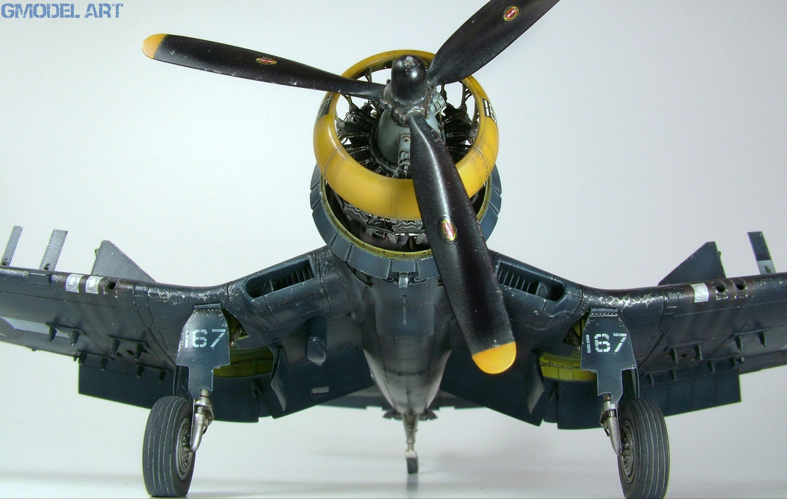
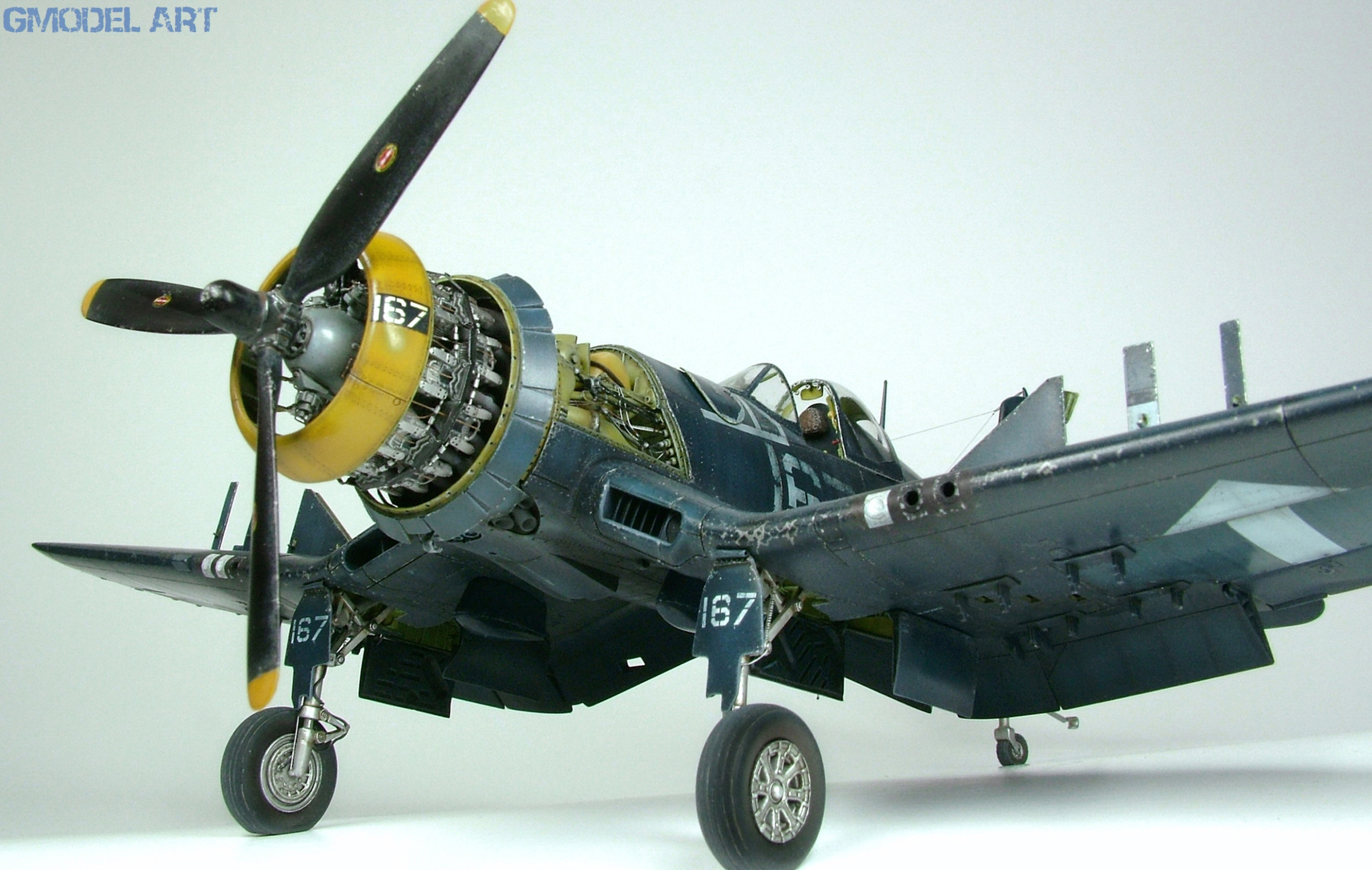
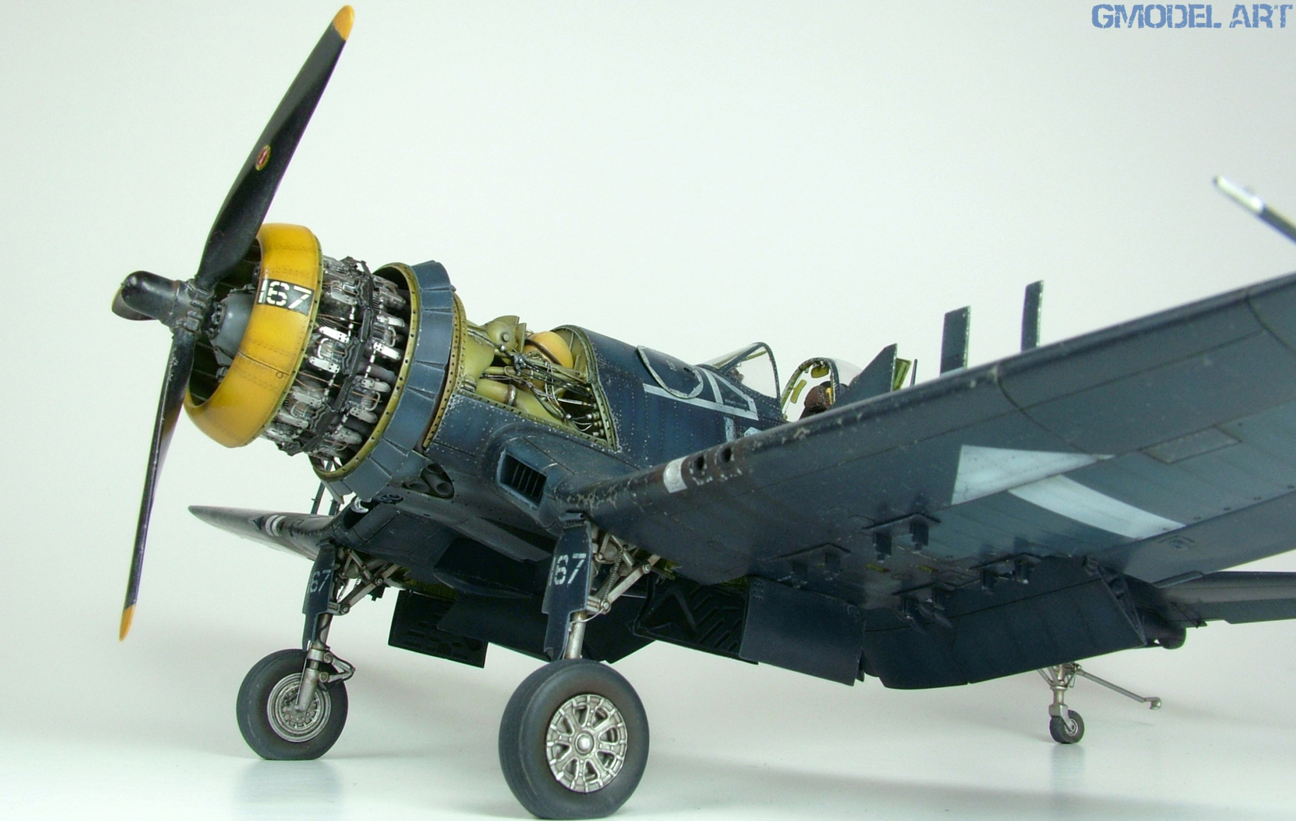
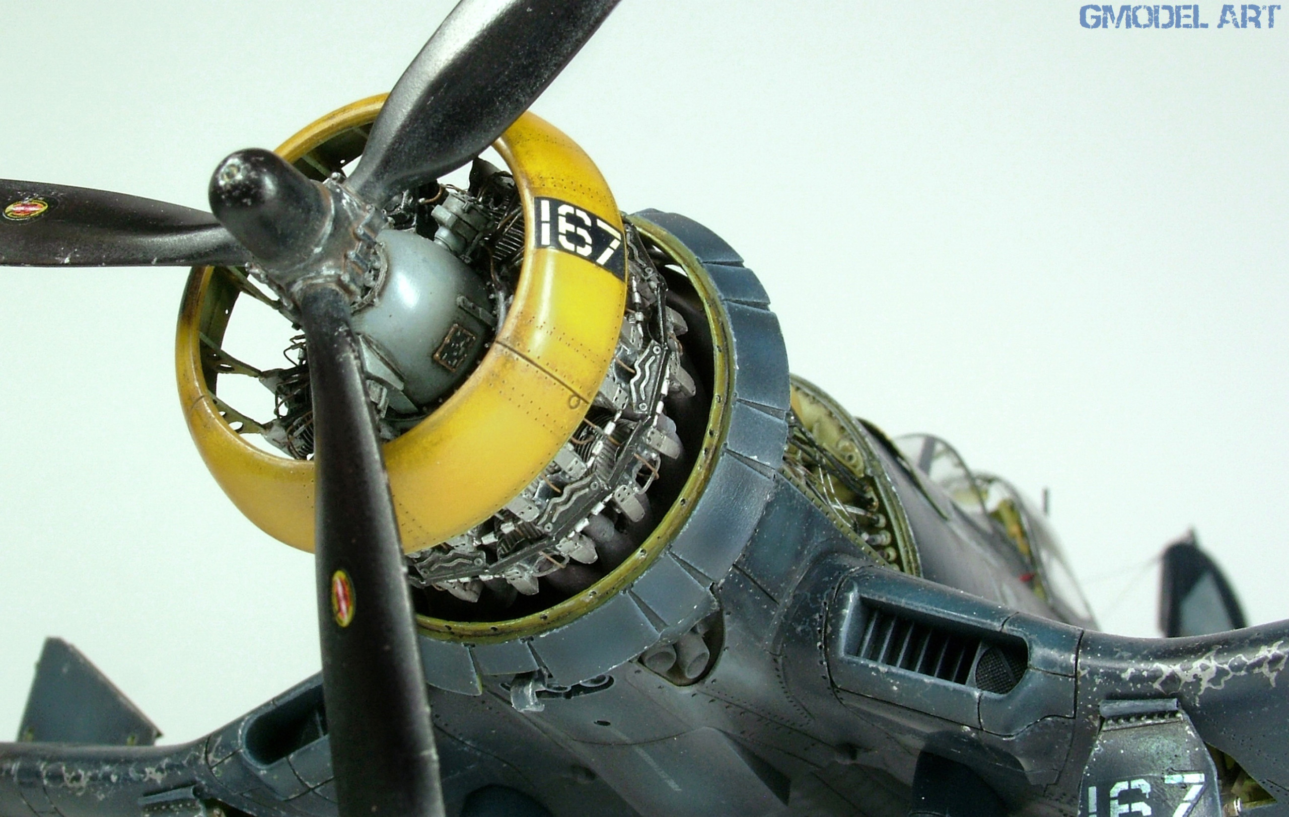
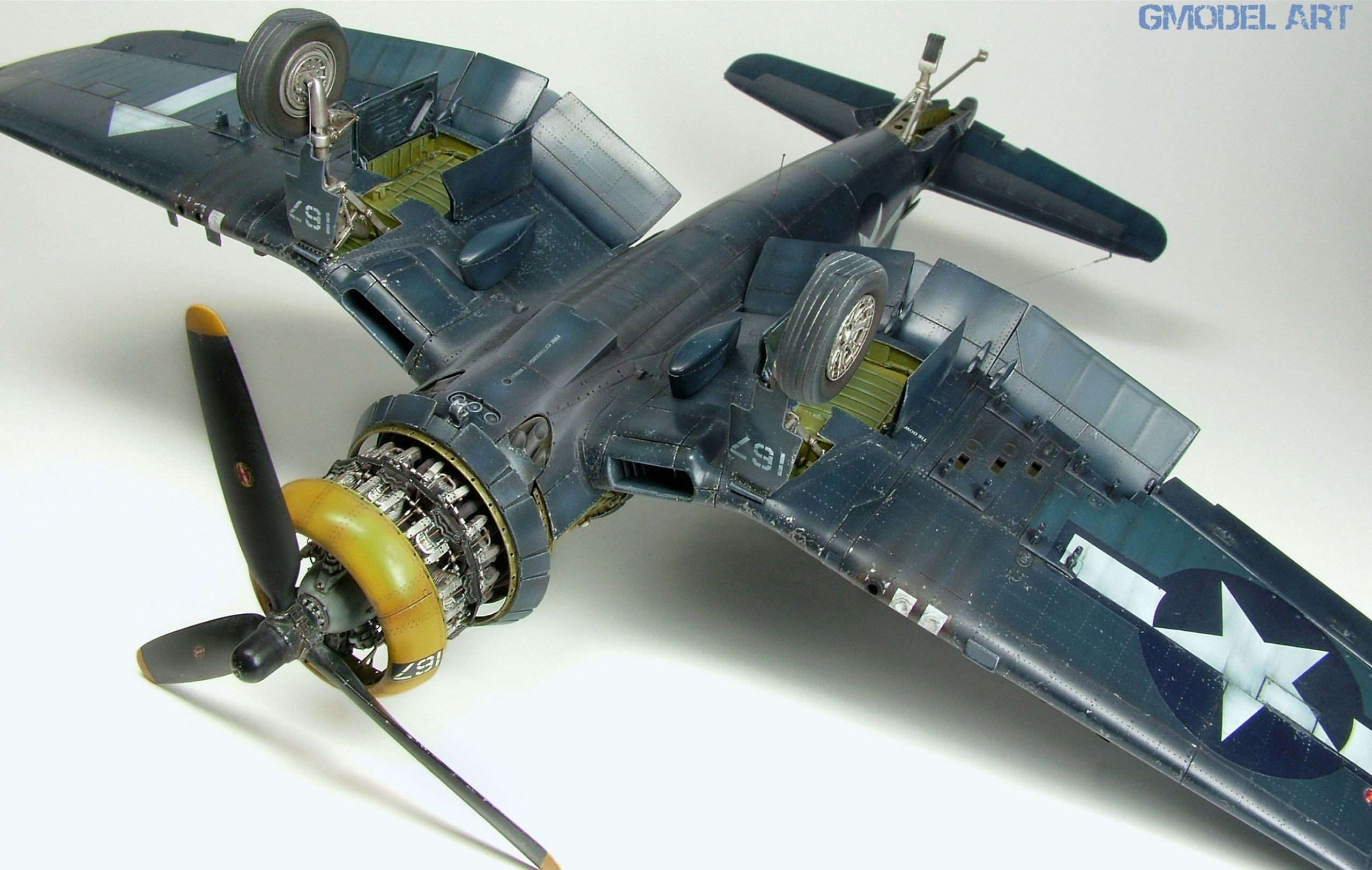
F4U-1D Corsair “white 167″PART 1
Construction:
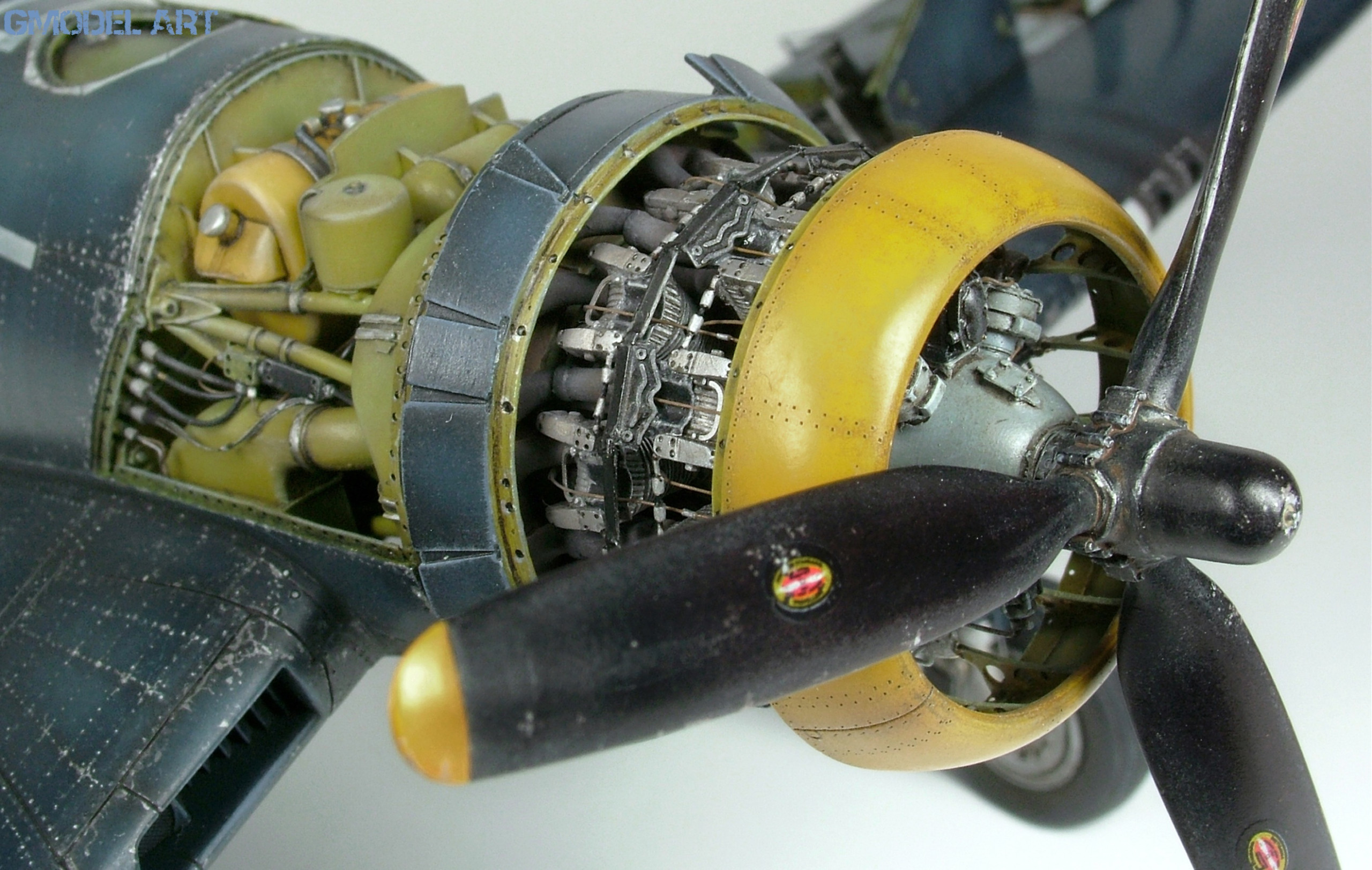
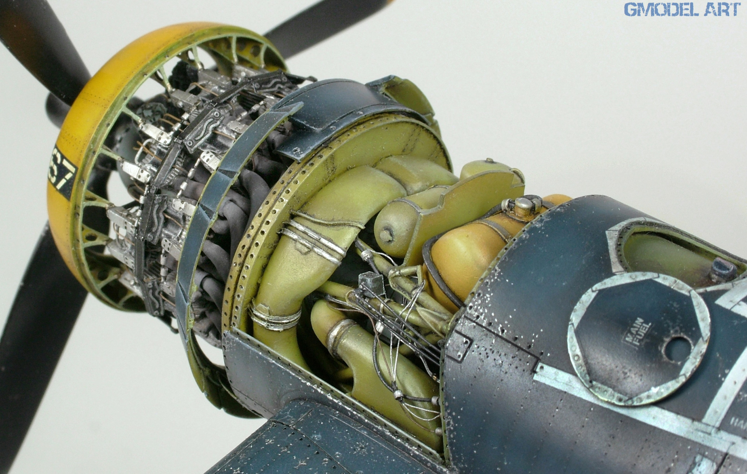
In the next few sentences I would like to explain certain fixes and possible complications with individual configurations and sections that await us during the construction of this type of uncovered model.
The combination of Tamiya’s kit and Aires detailed set is possibly the best variation that we can come across. However, this variation does not allow much room for further modifications or other improvements with hand-made parts….
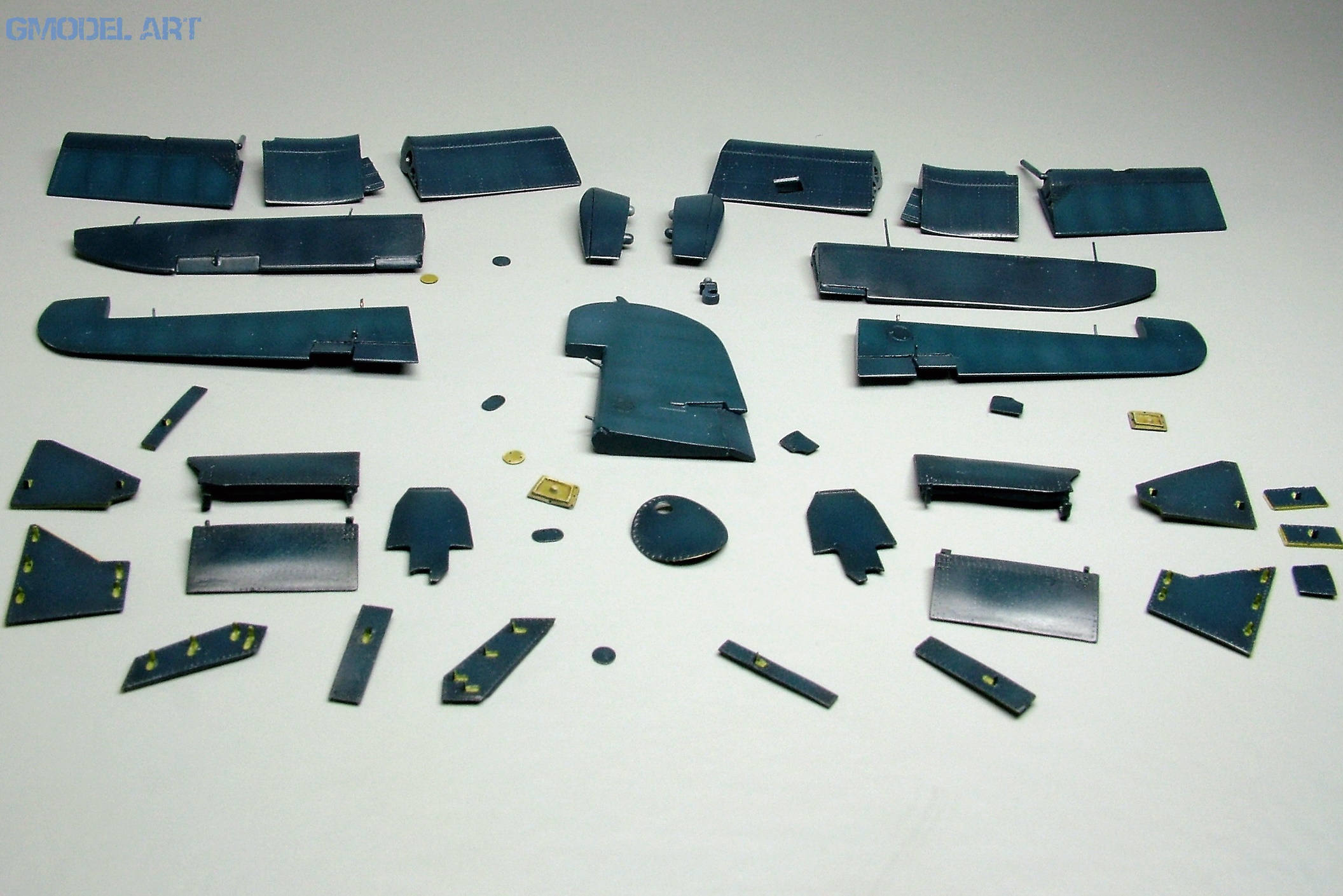
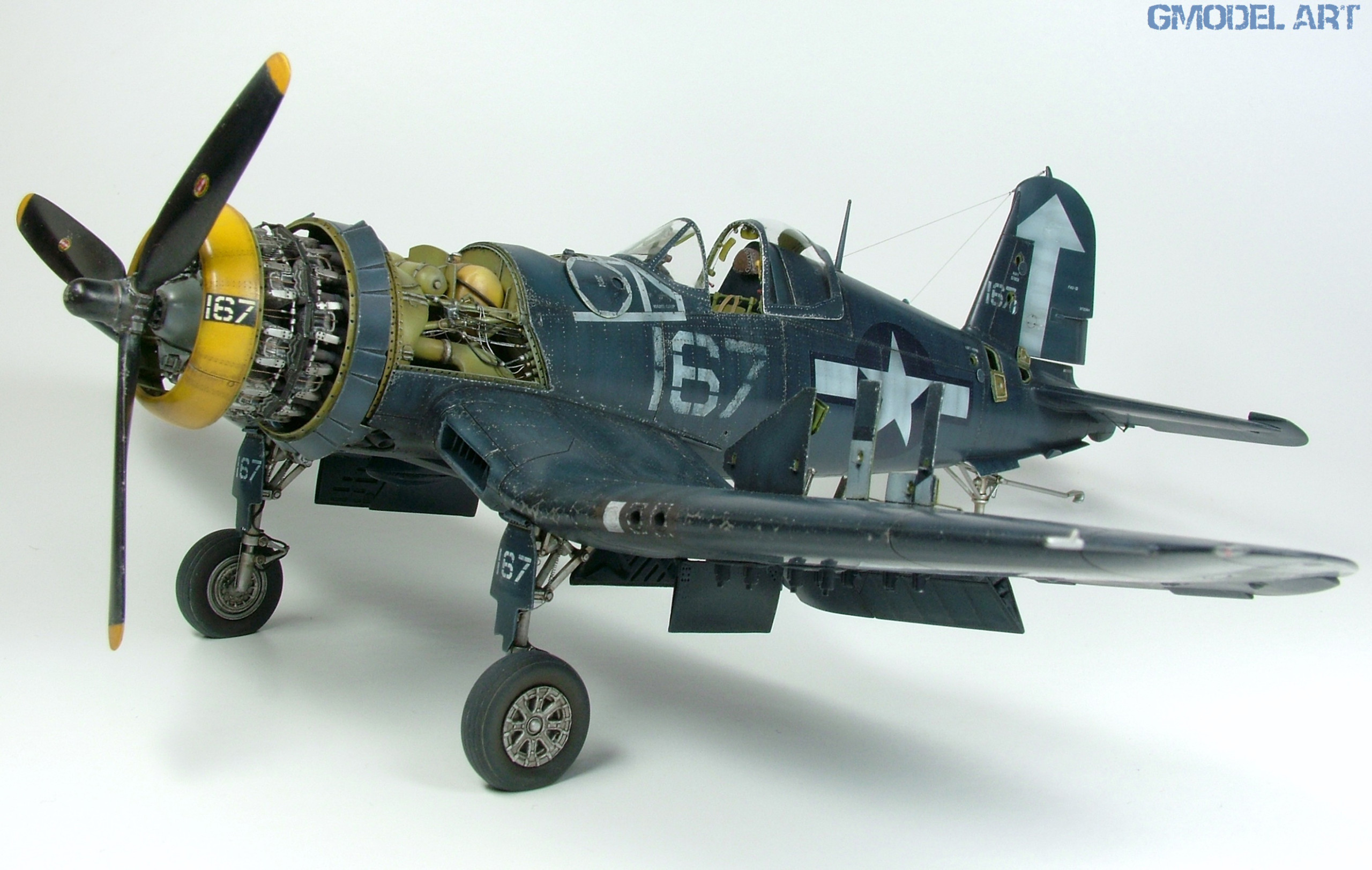
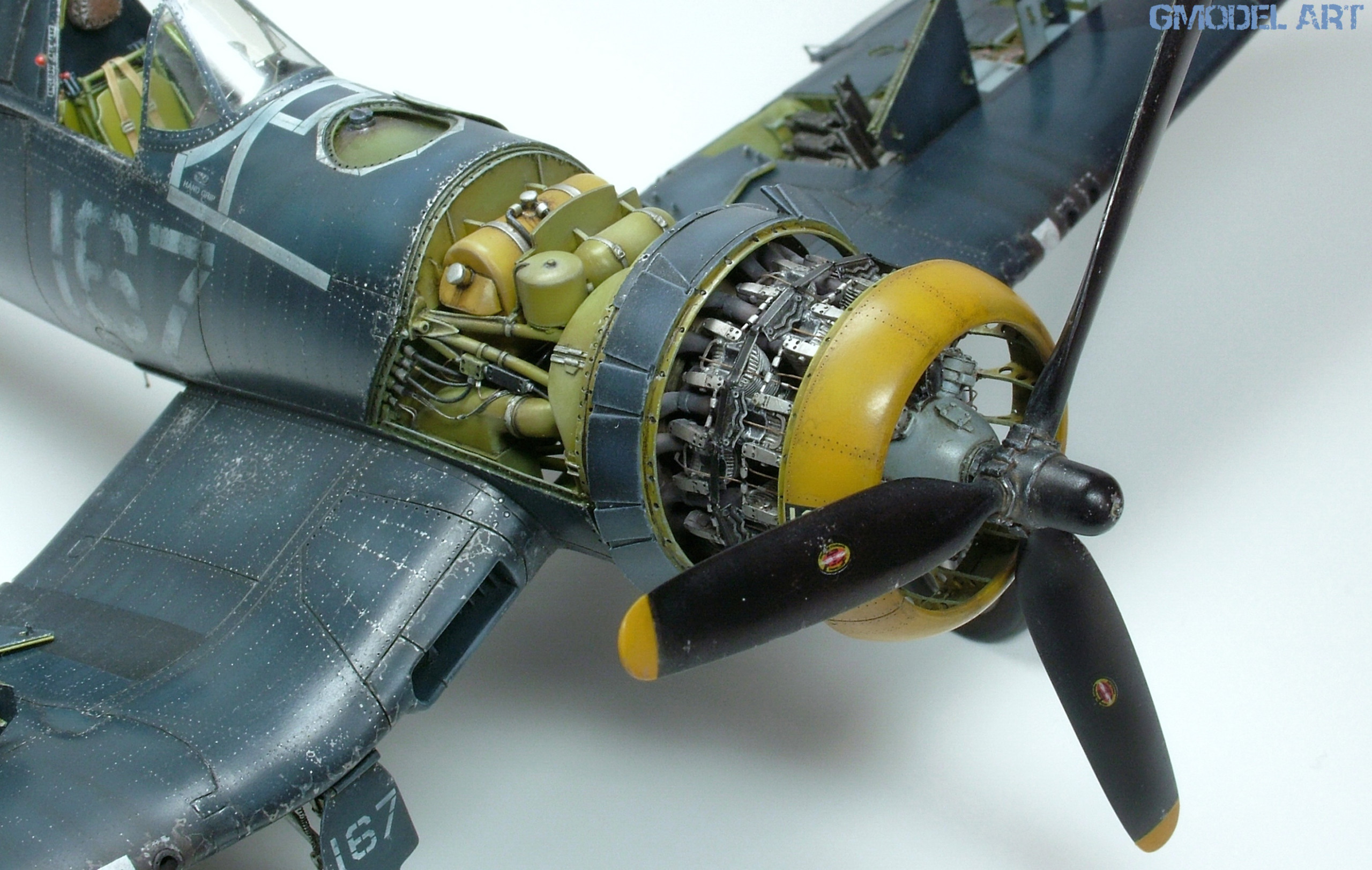
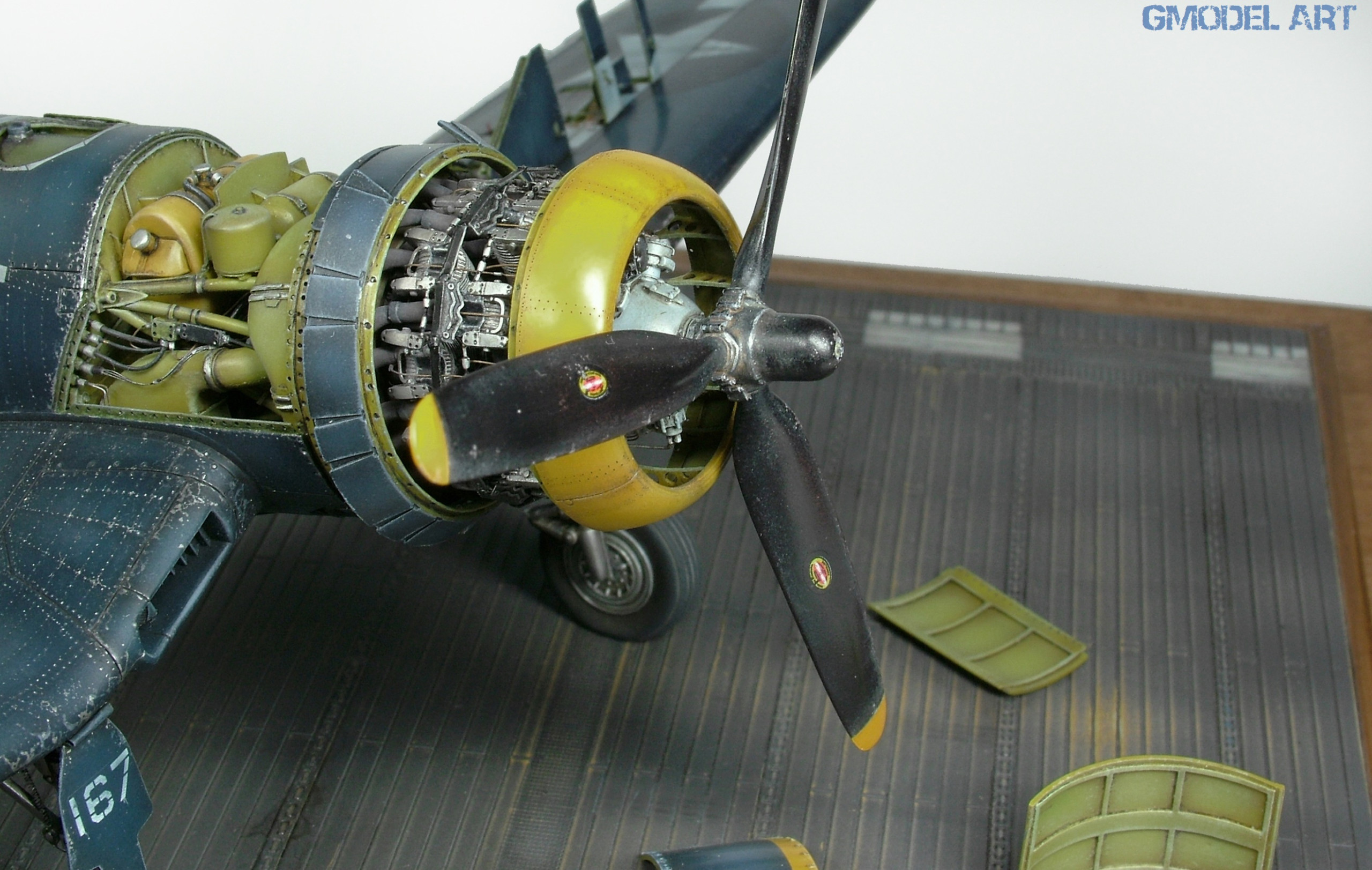
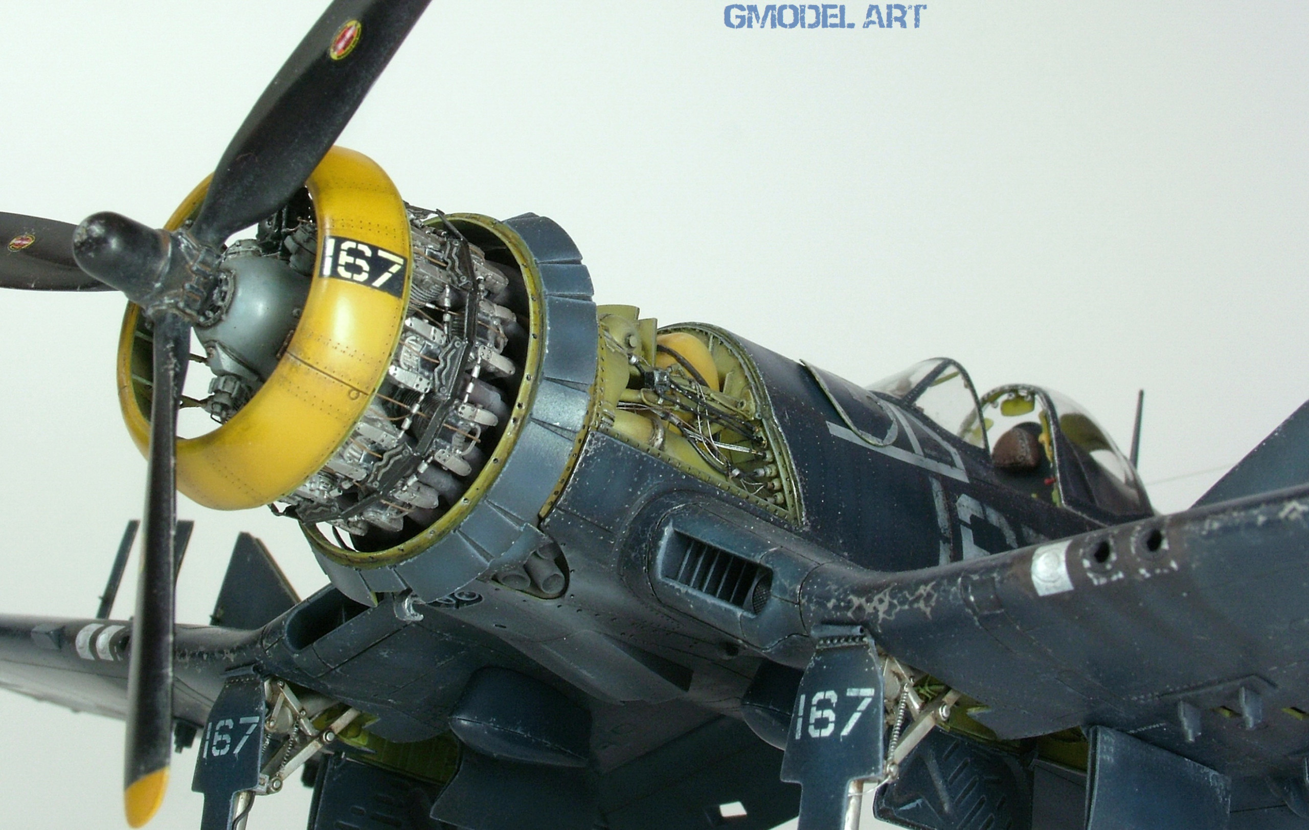
After cleaning all kit and Detailed set pieces, I gradually sorted them out into individual subassemblies (boxes), for a better perspective (fuselage, wings, cockpit, weapons, under carriage, engine) and started constructing, moderate coloring and patina.
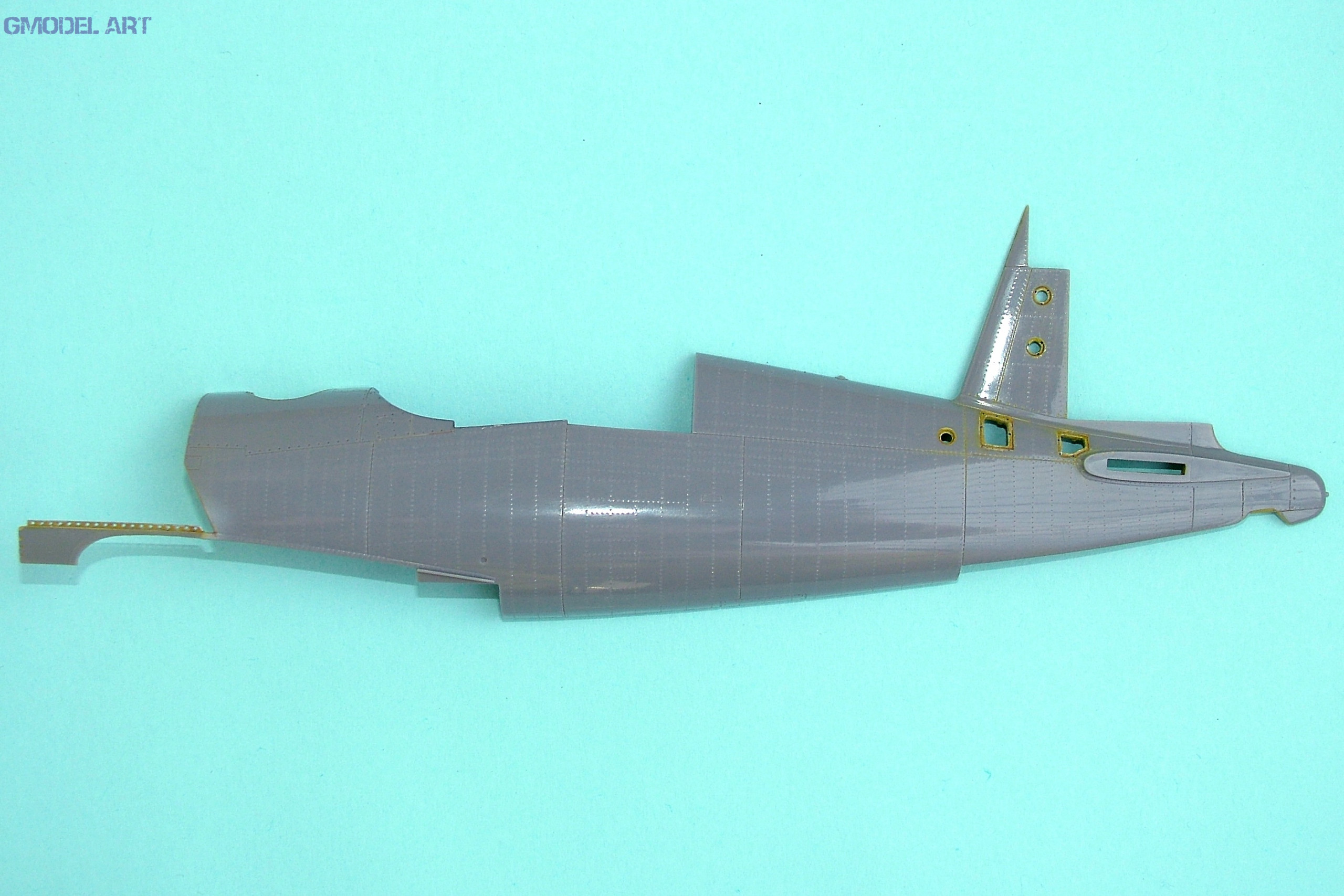
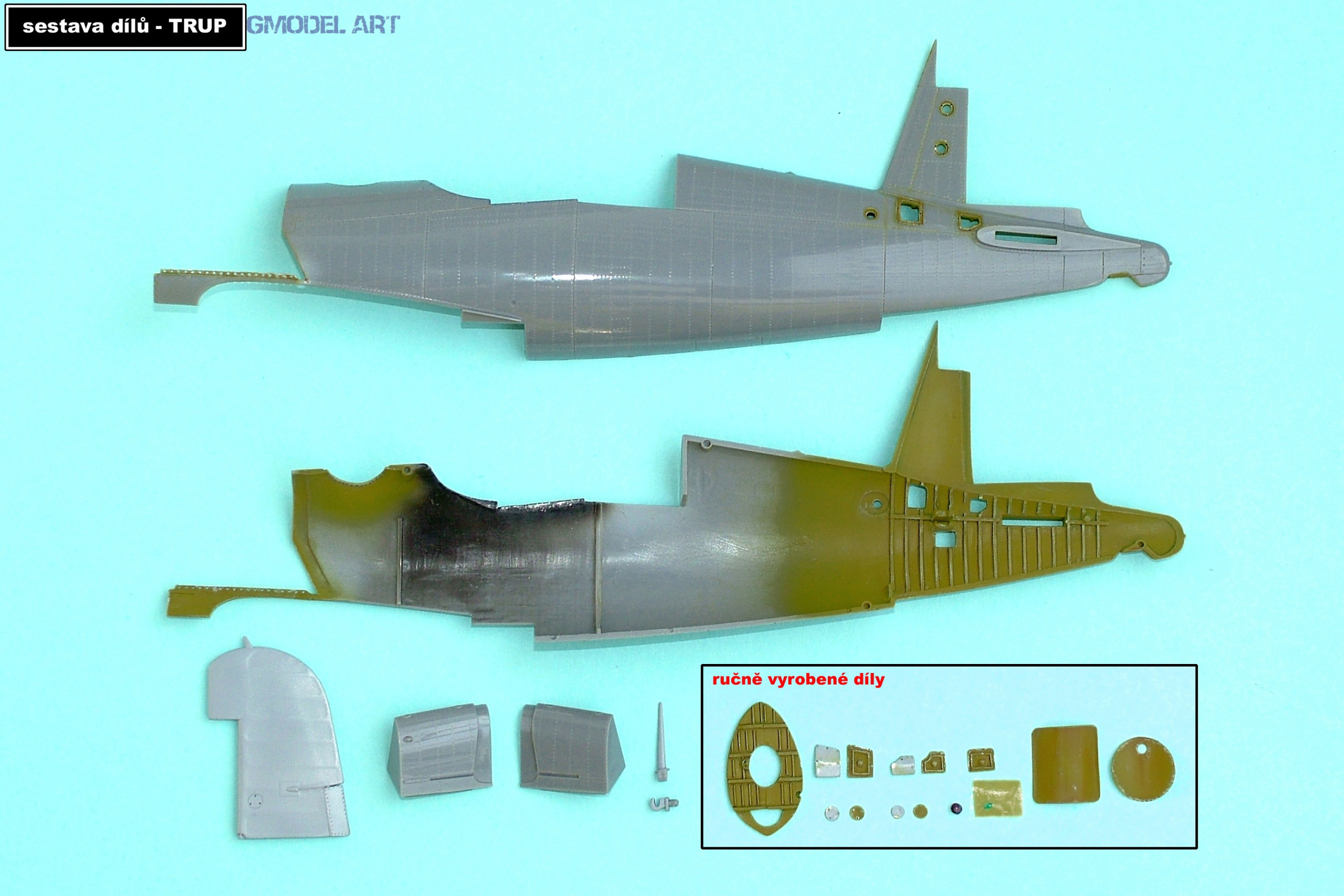
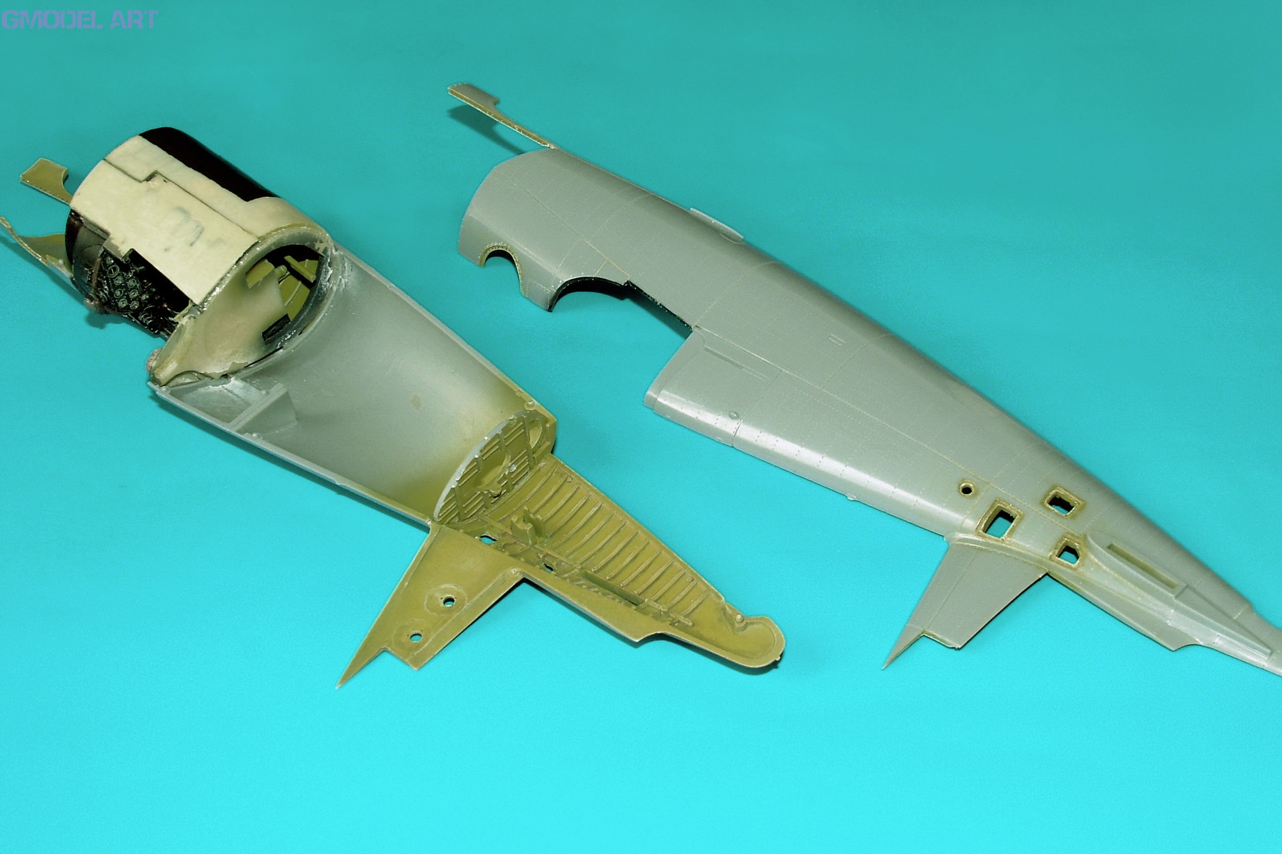
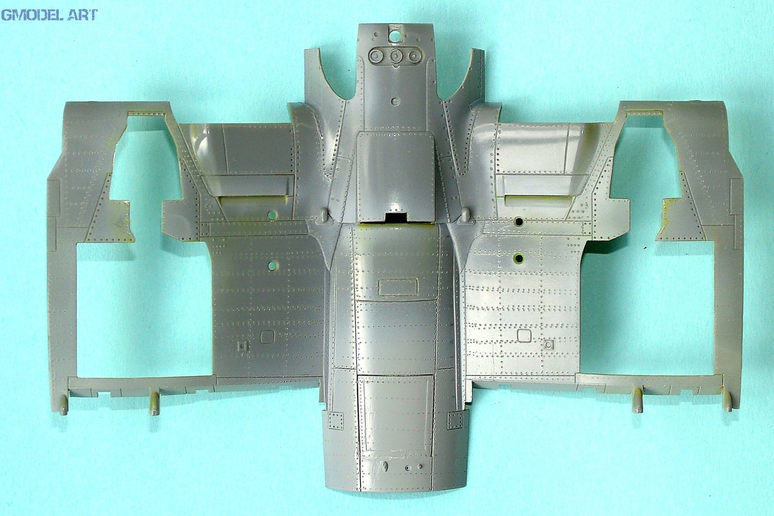
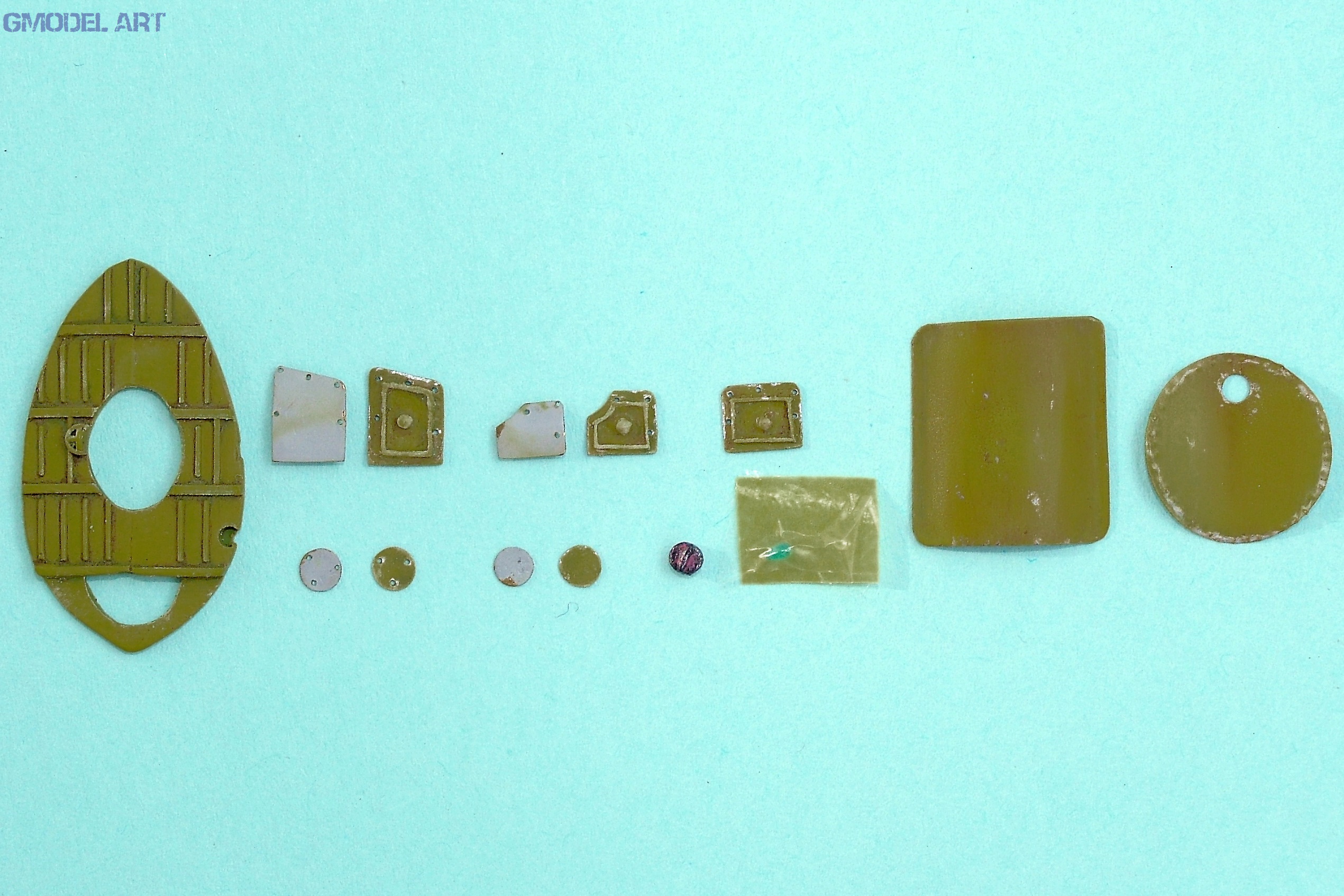
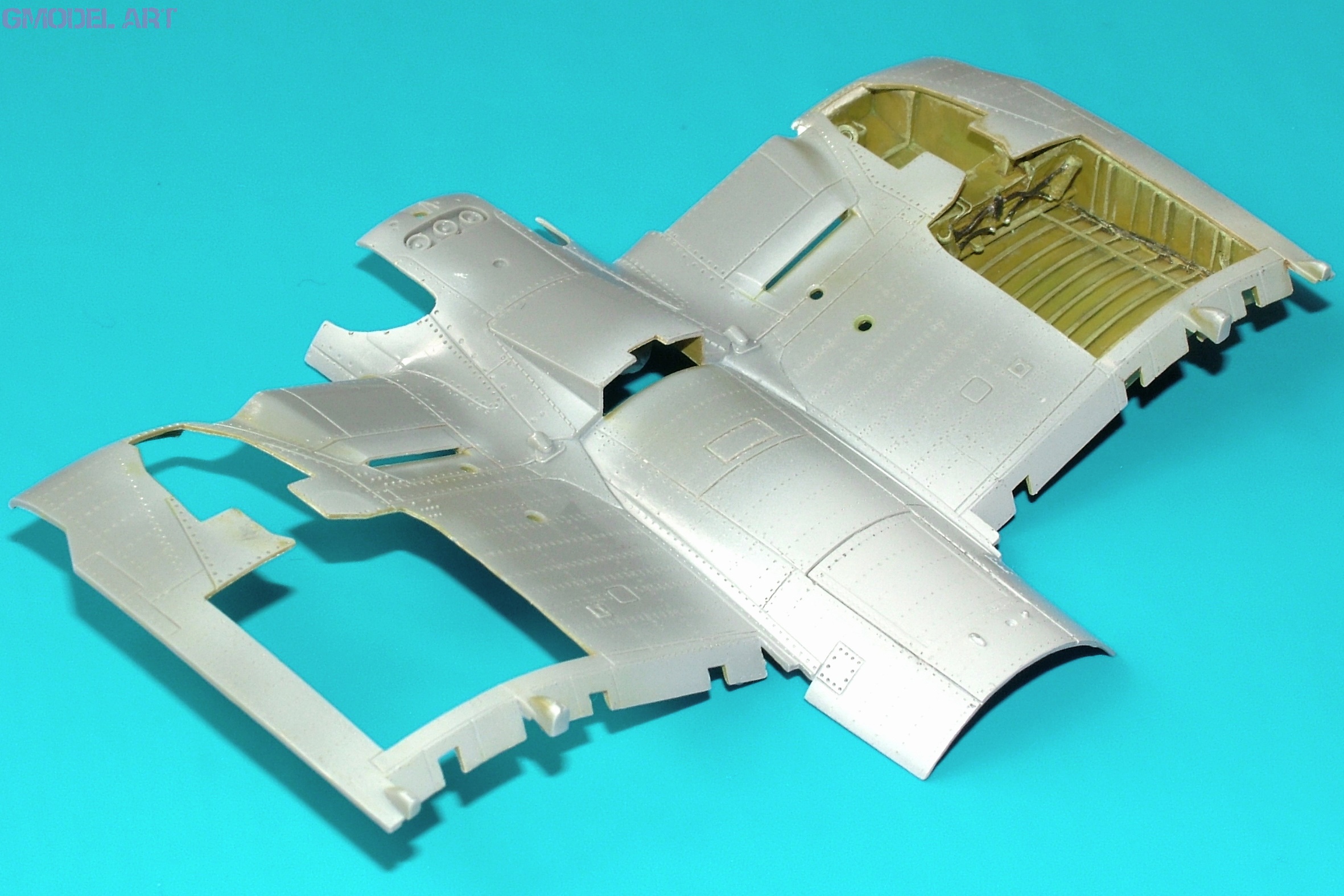
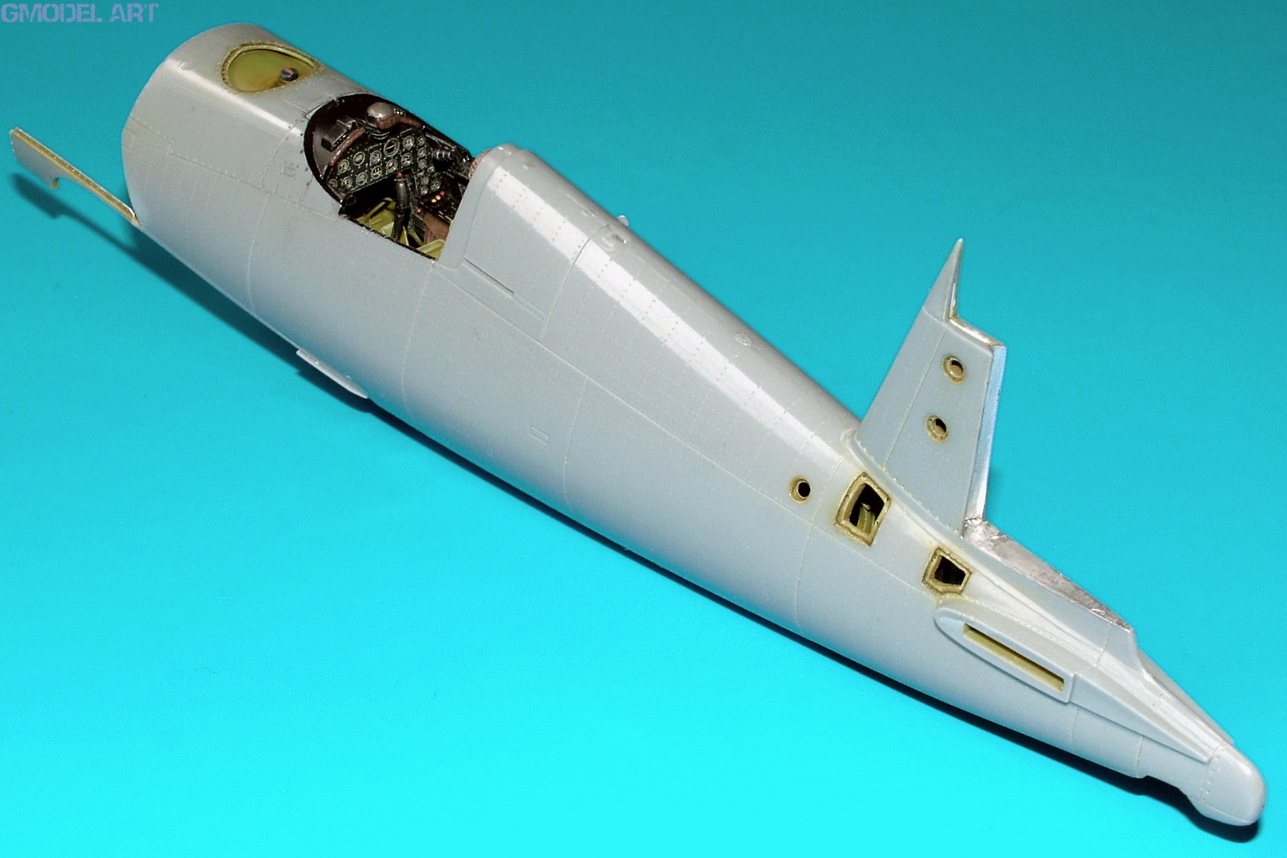
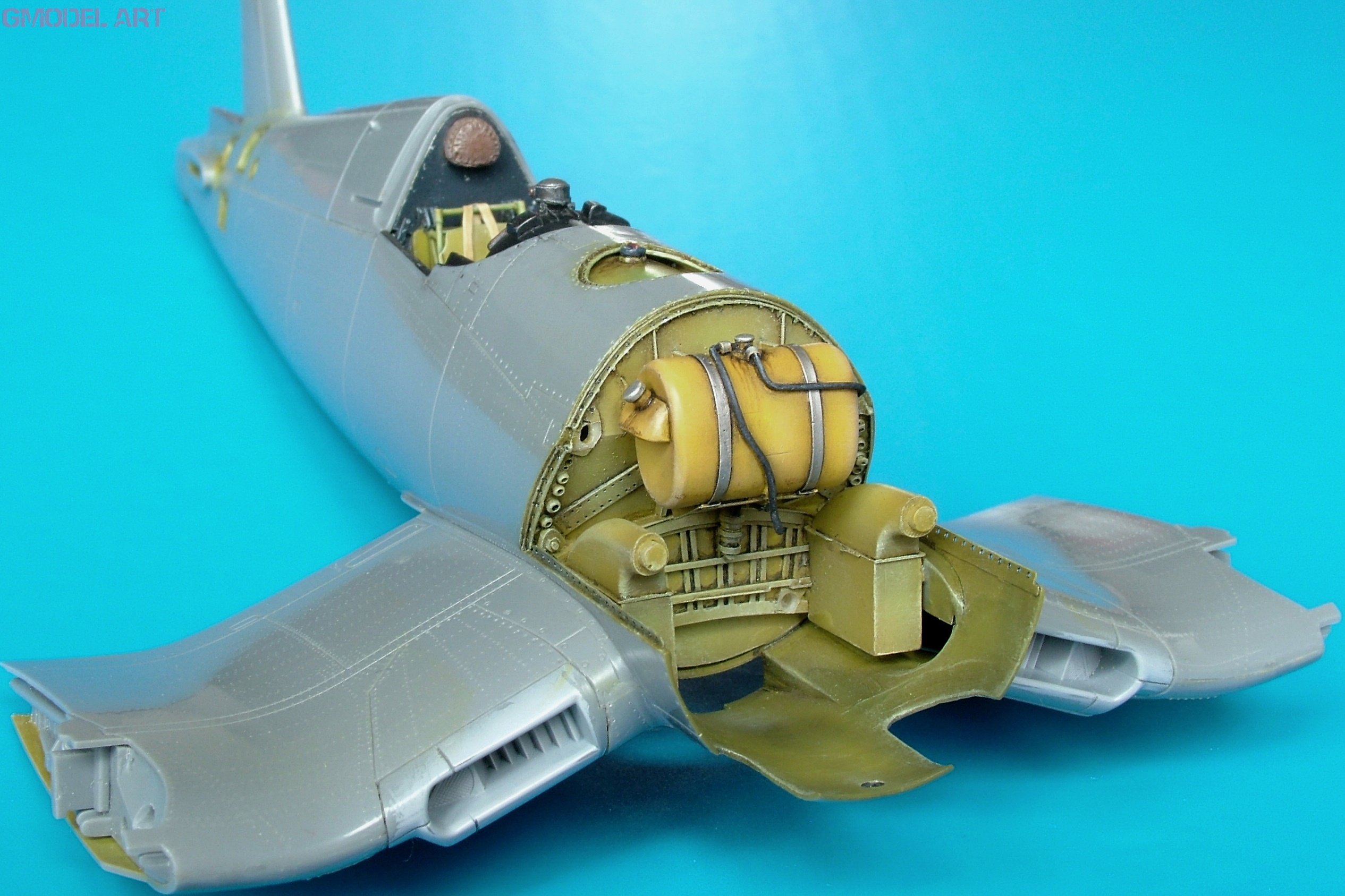
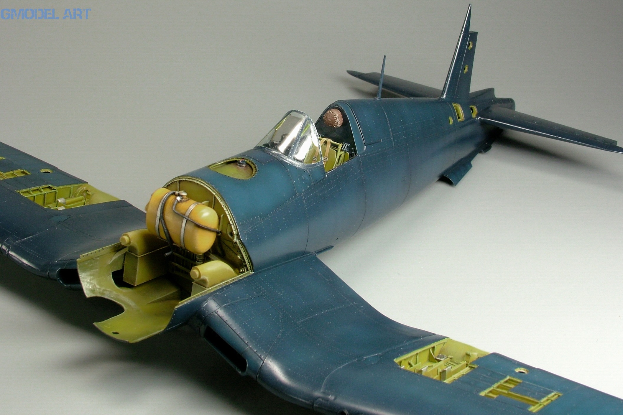
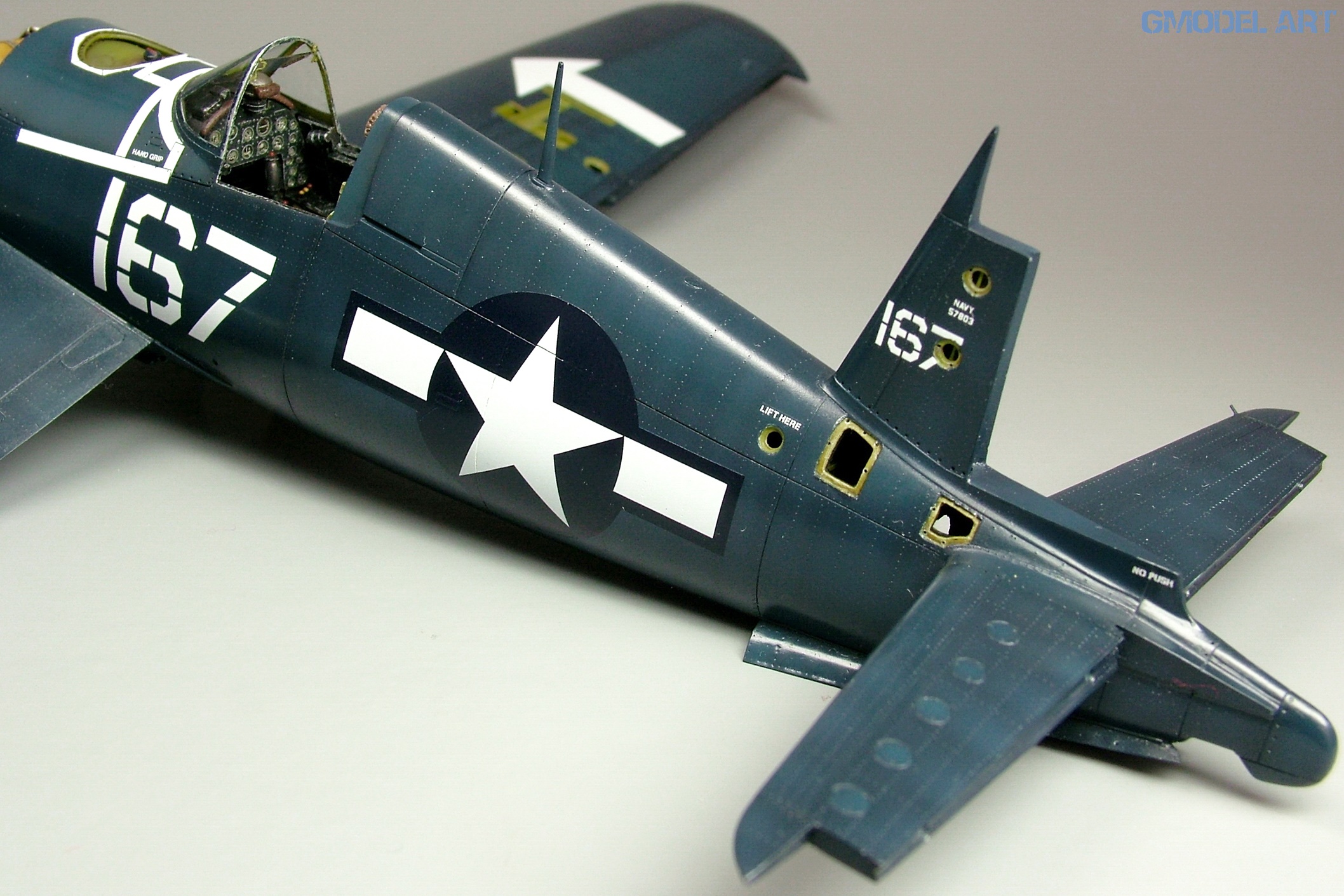
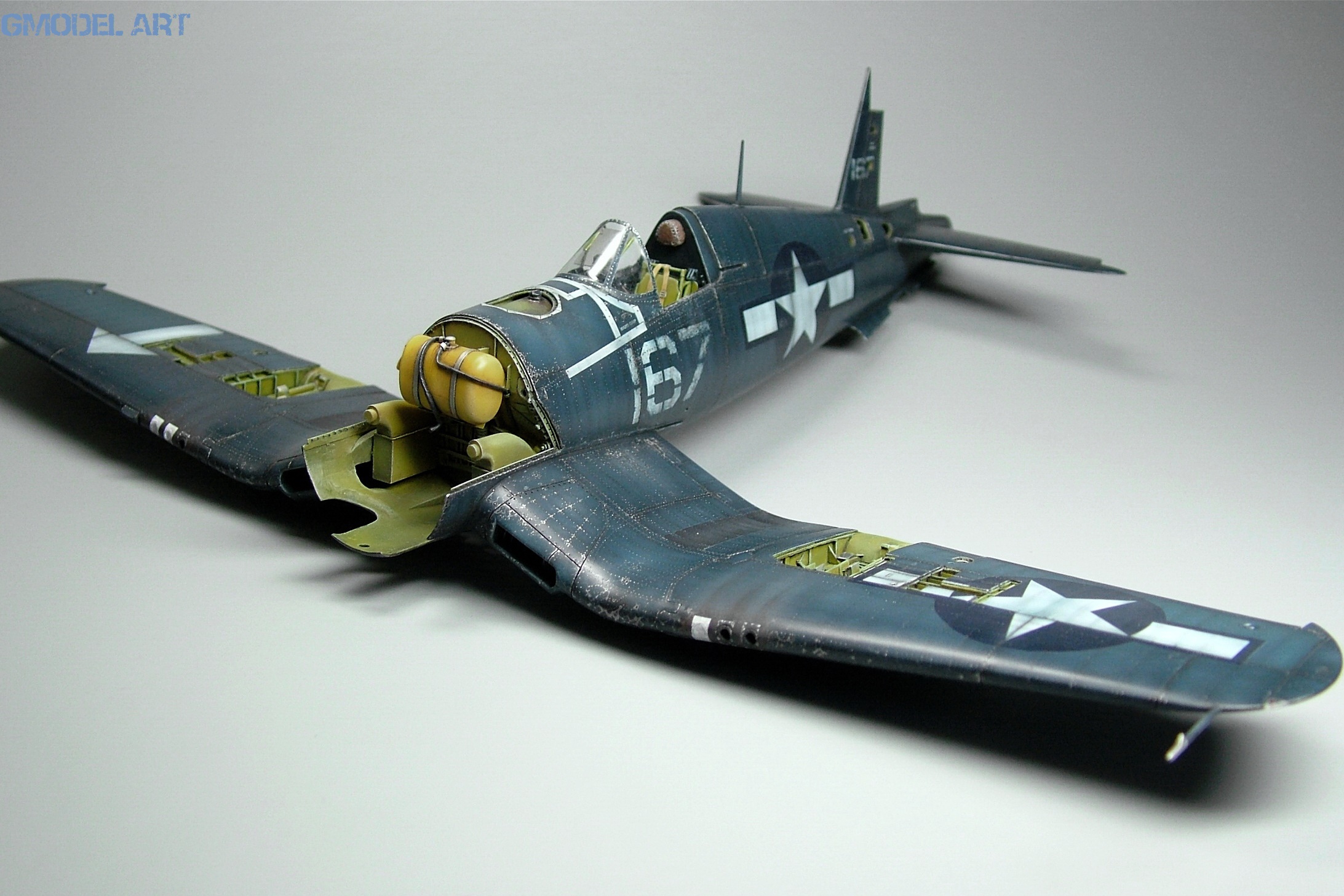
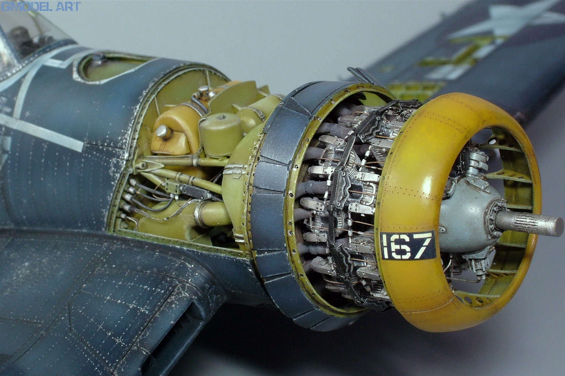
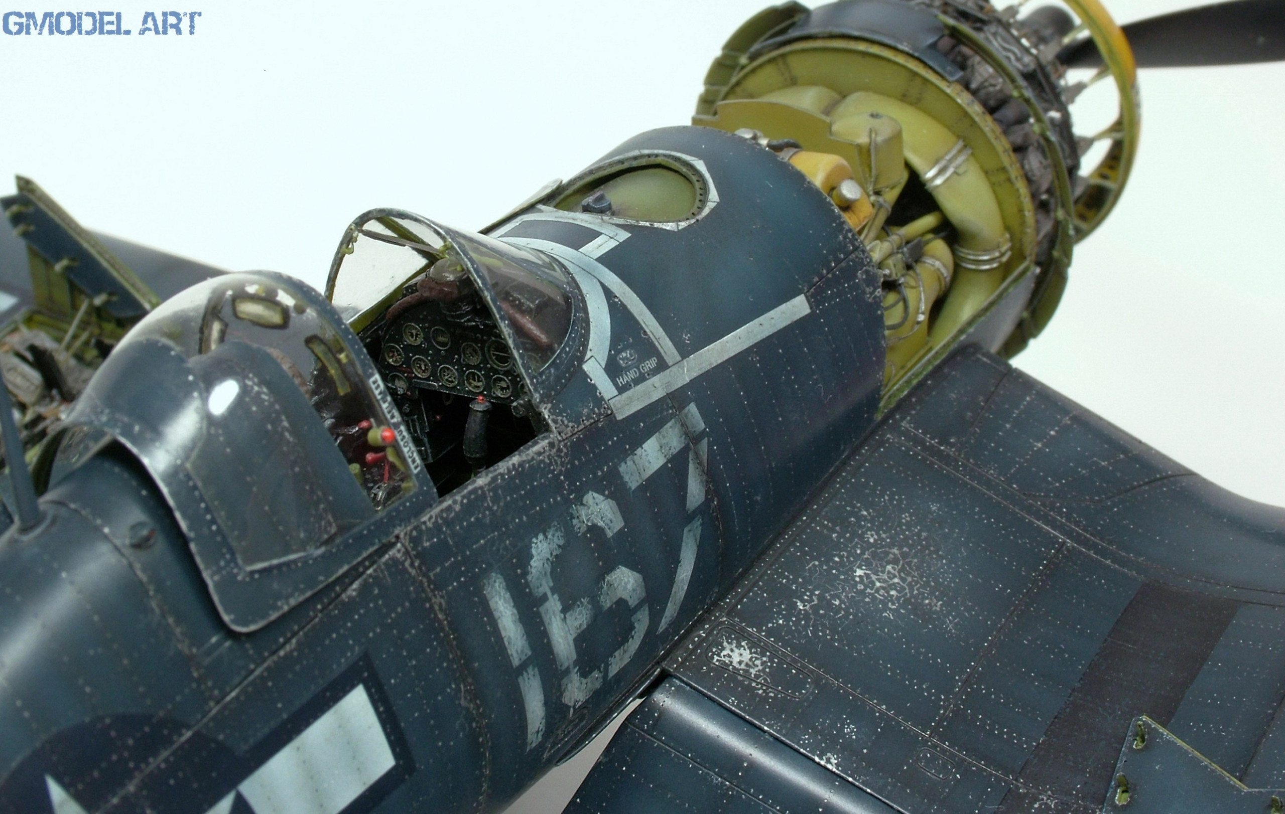
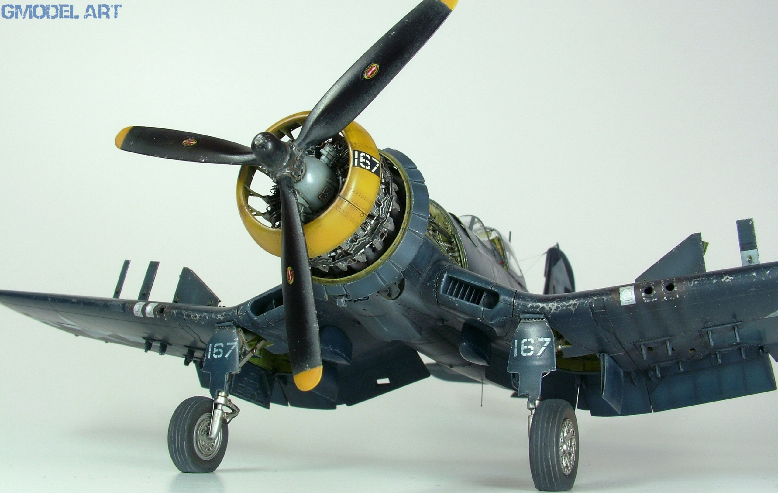
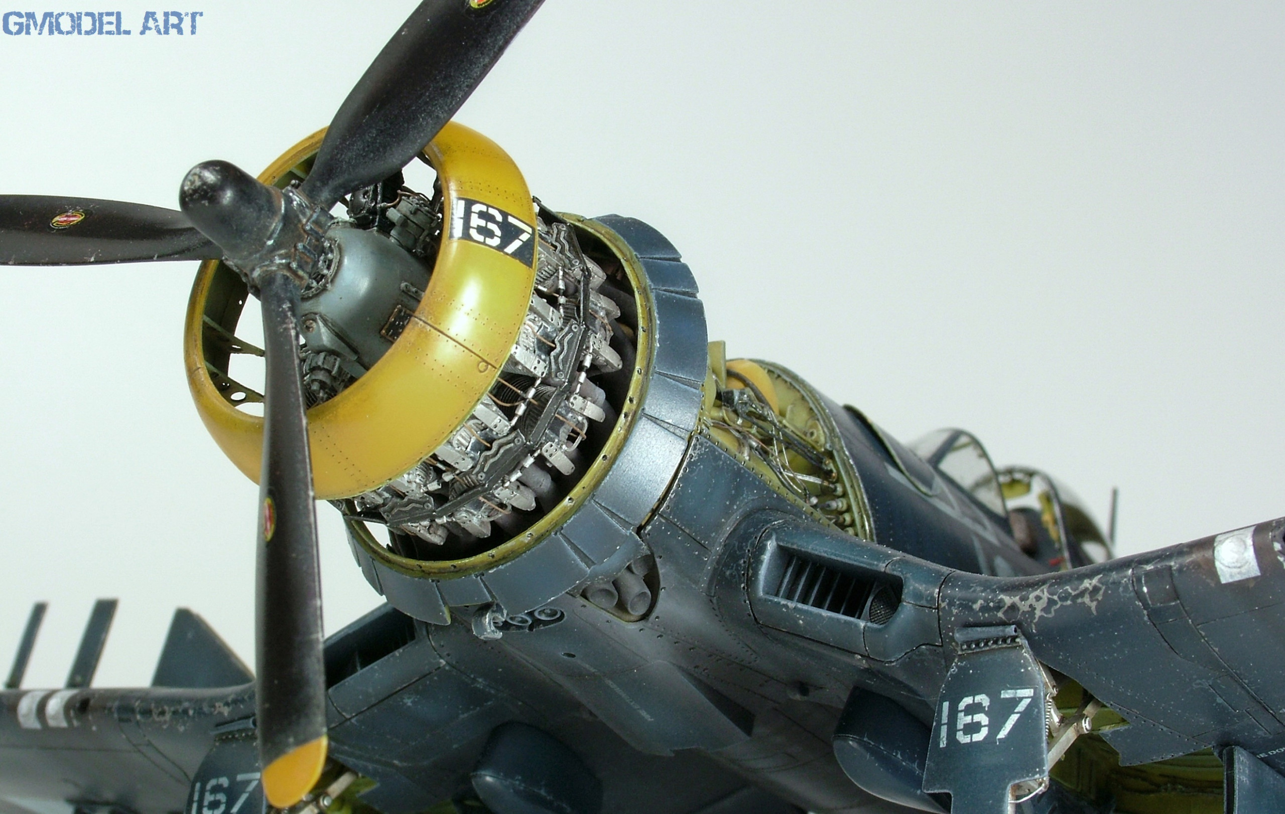
1. Fuselage:
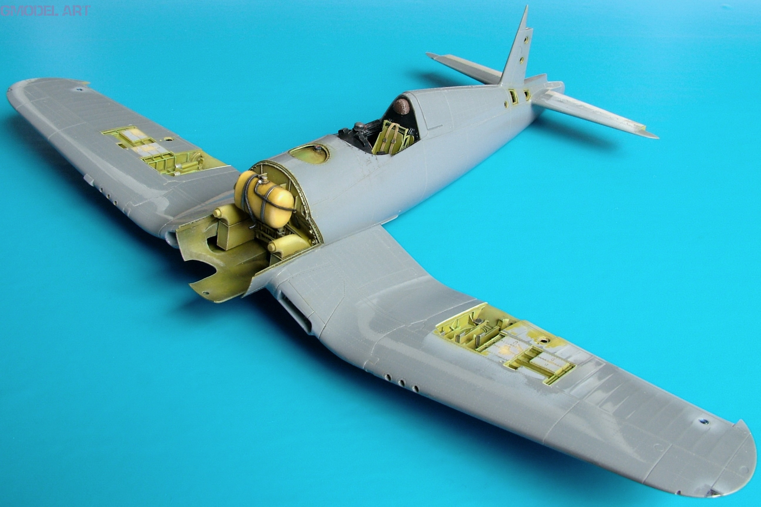
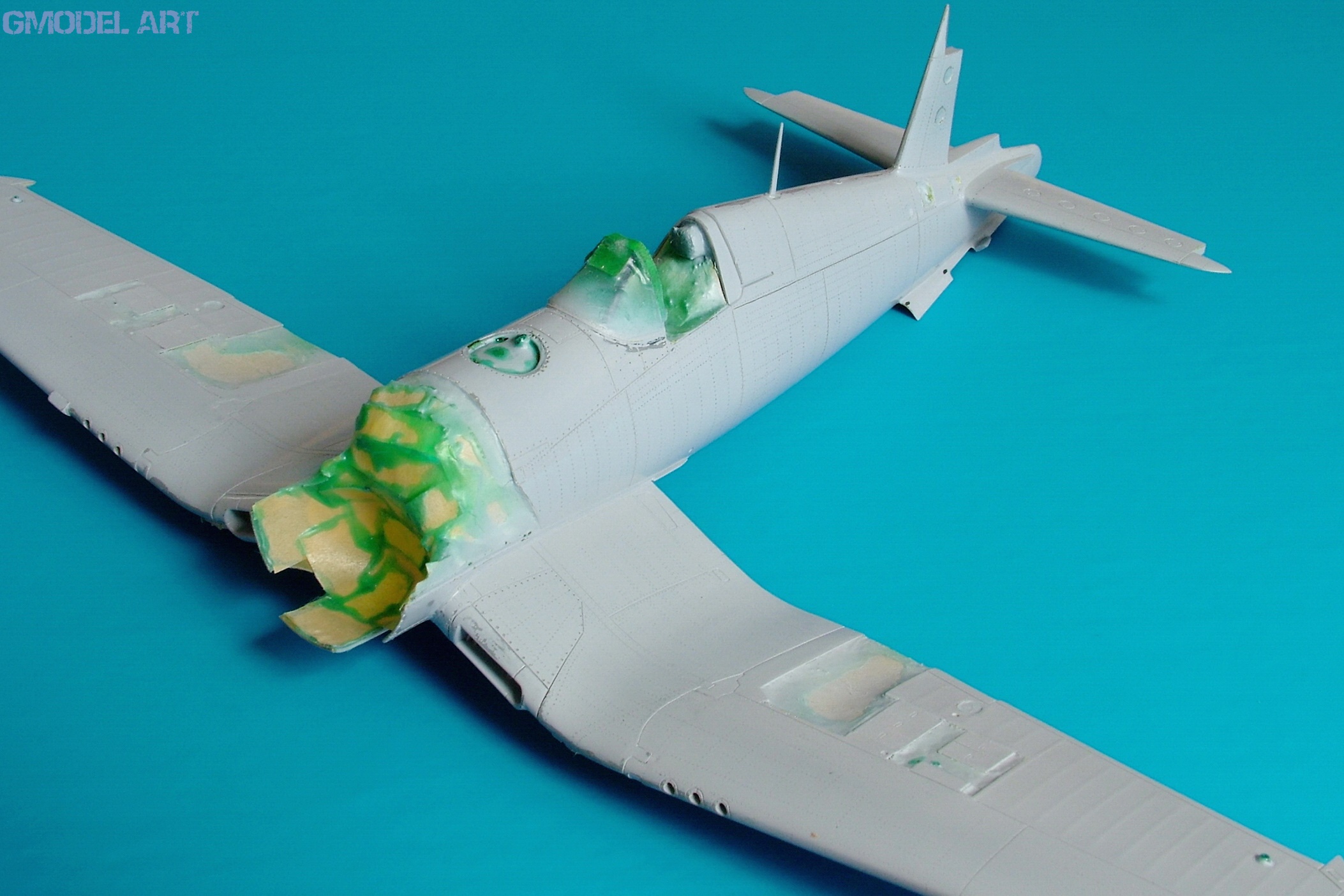
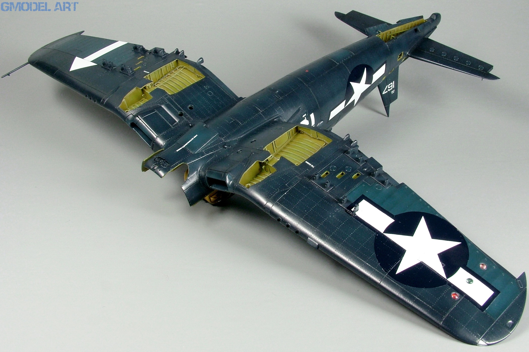
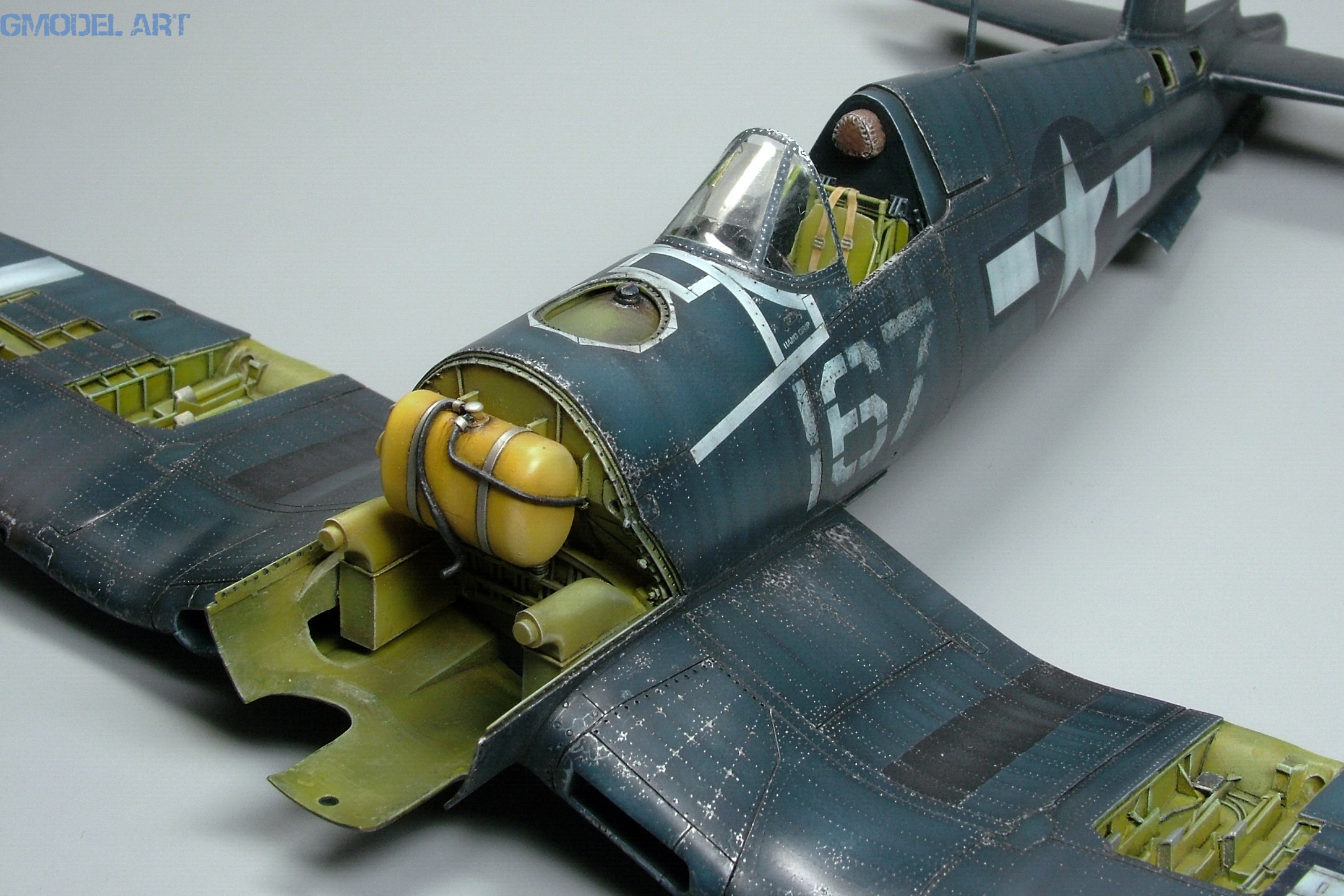
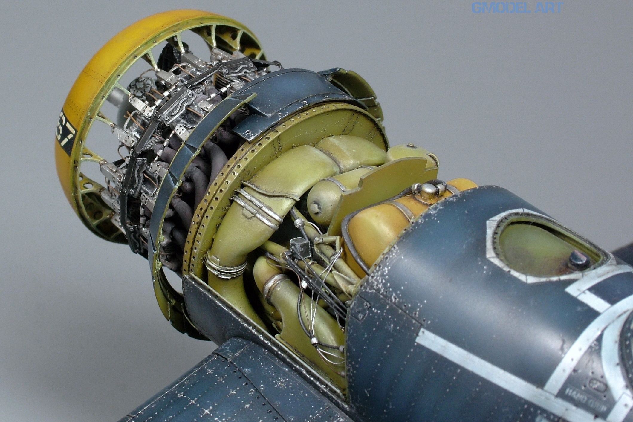
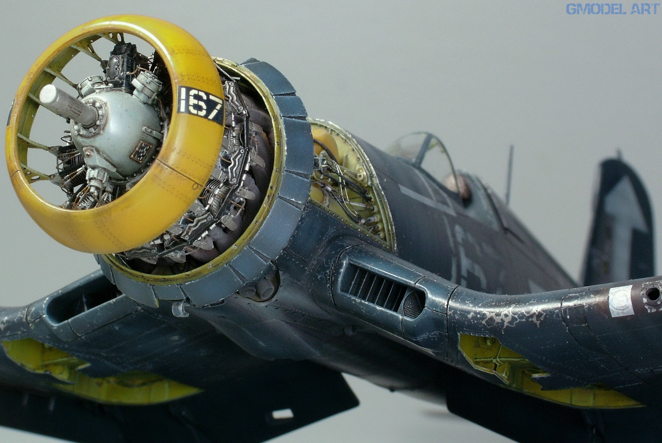
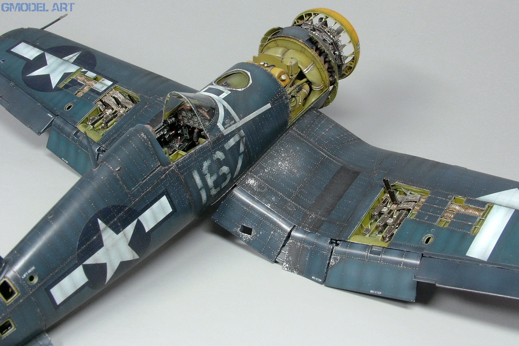
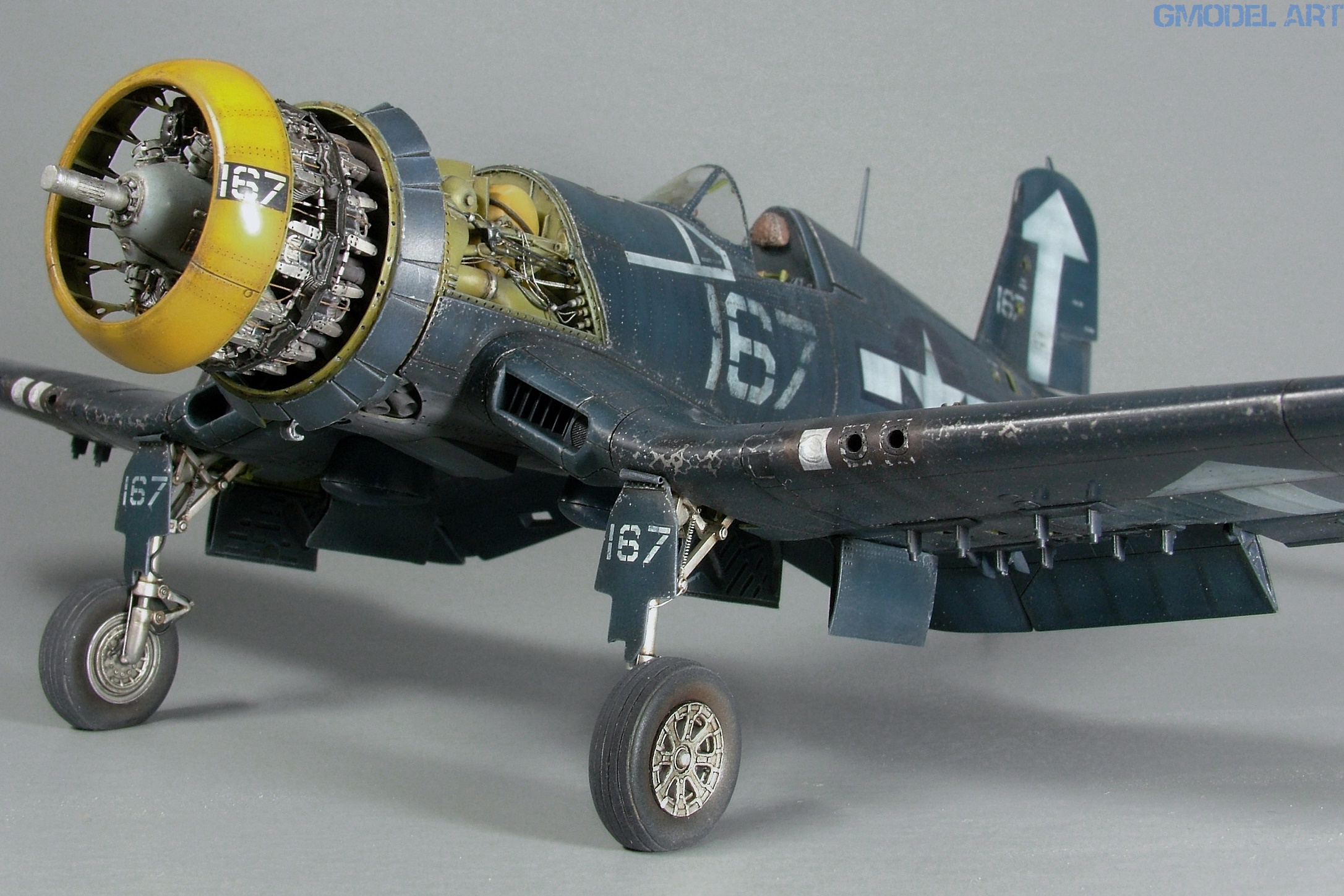
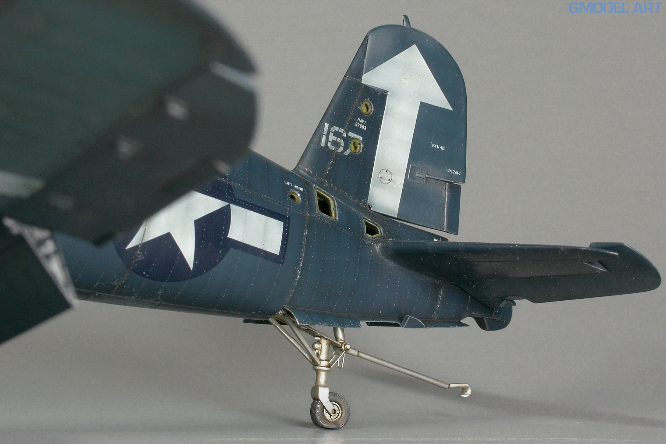
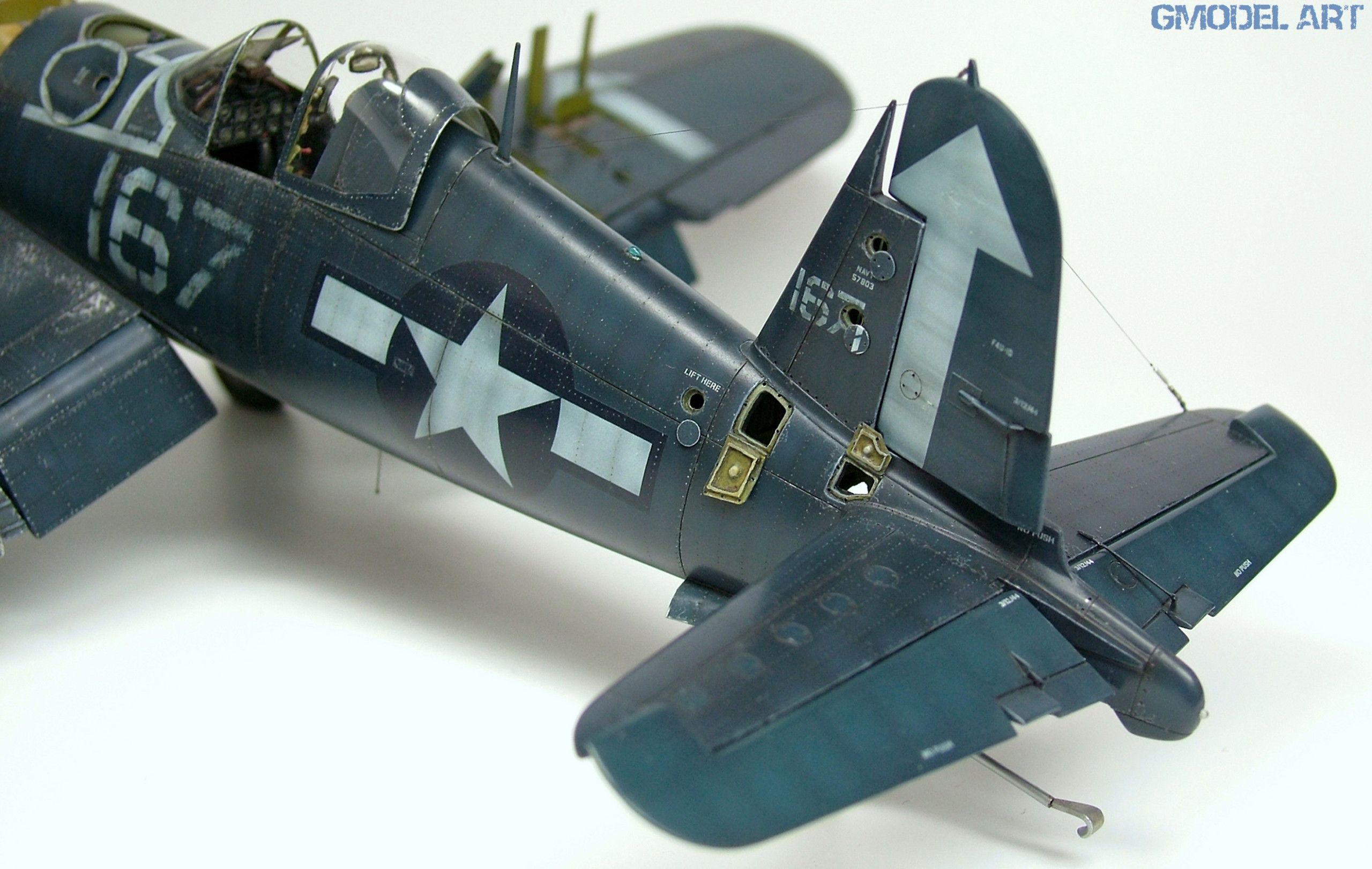
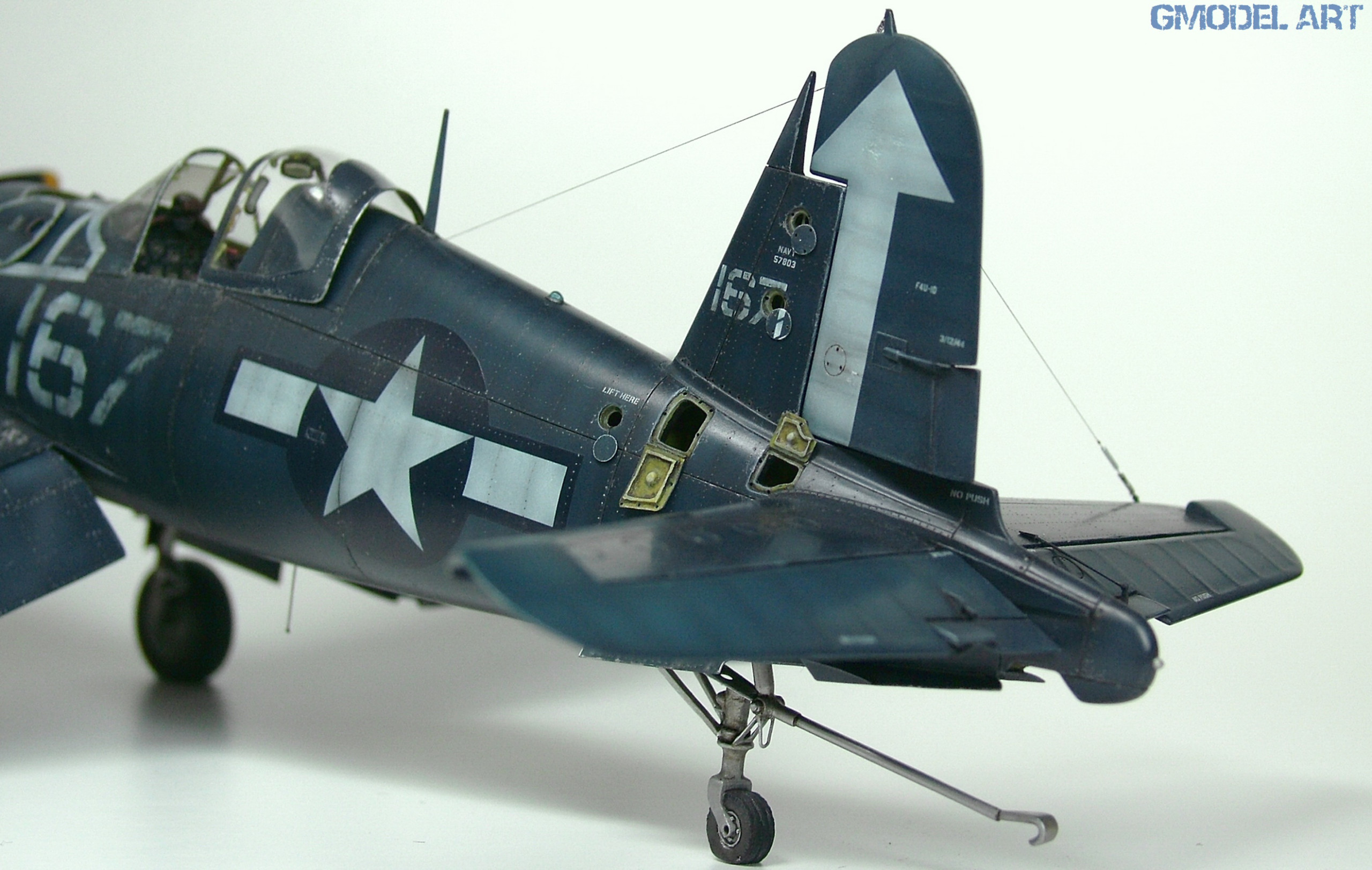
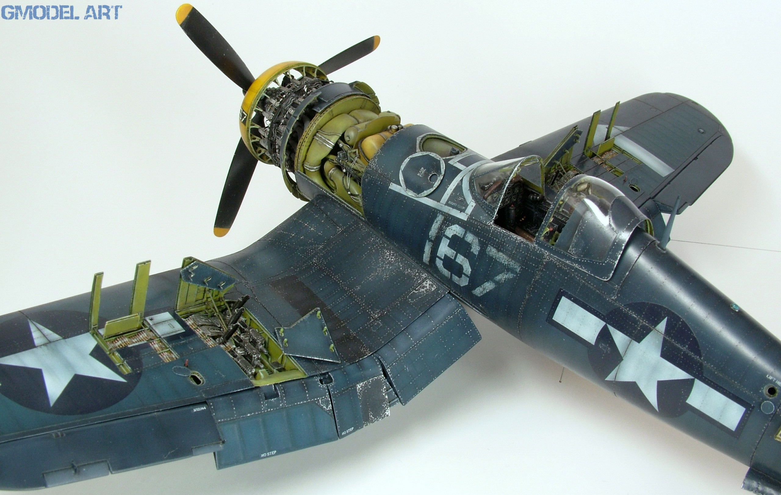
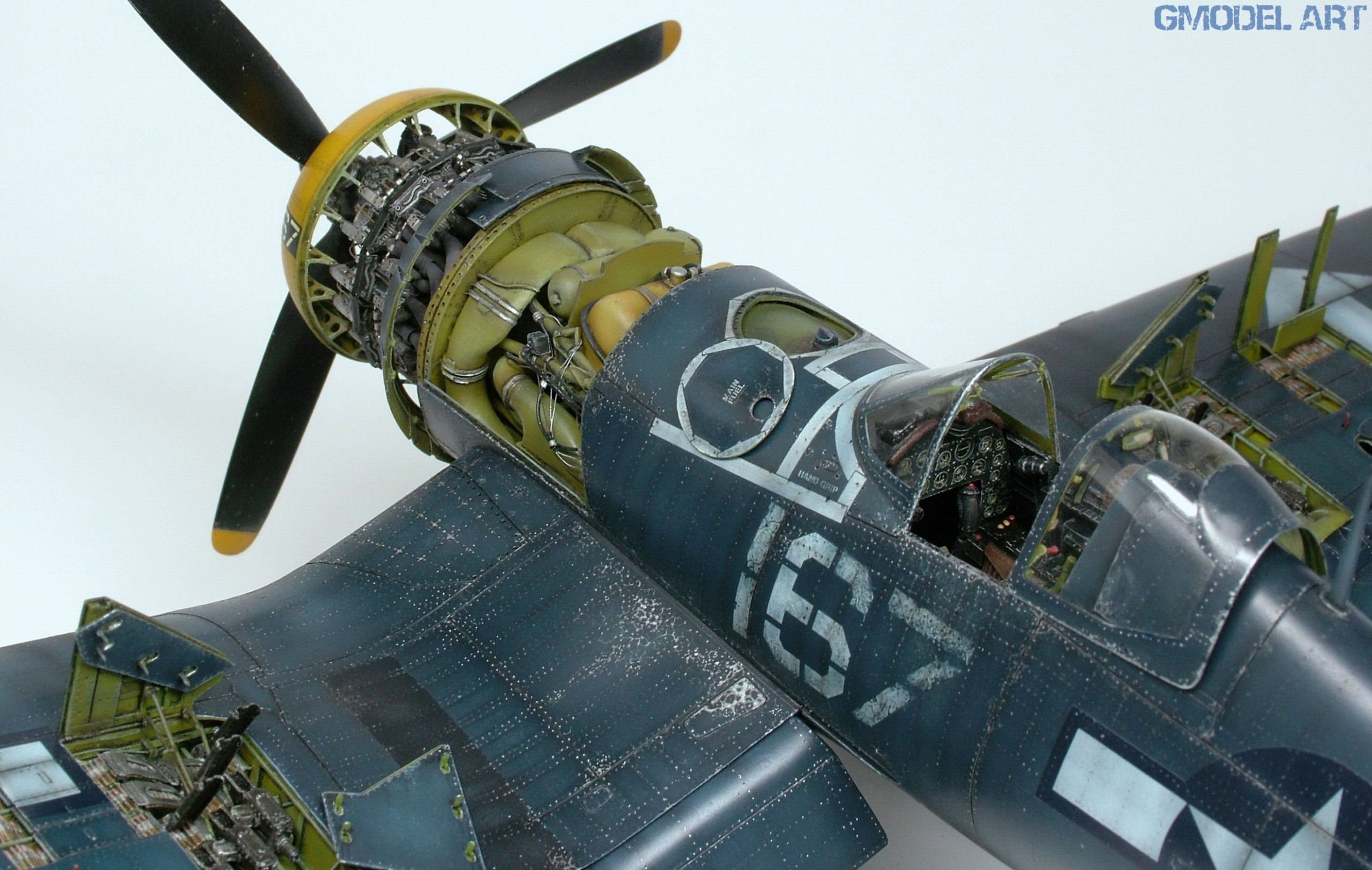
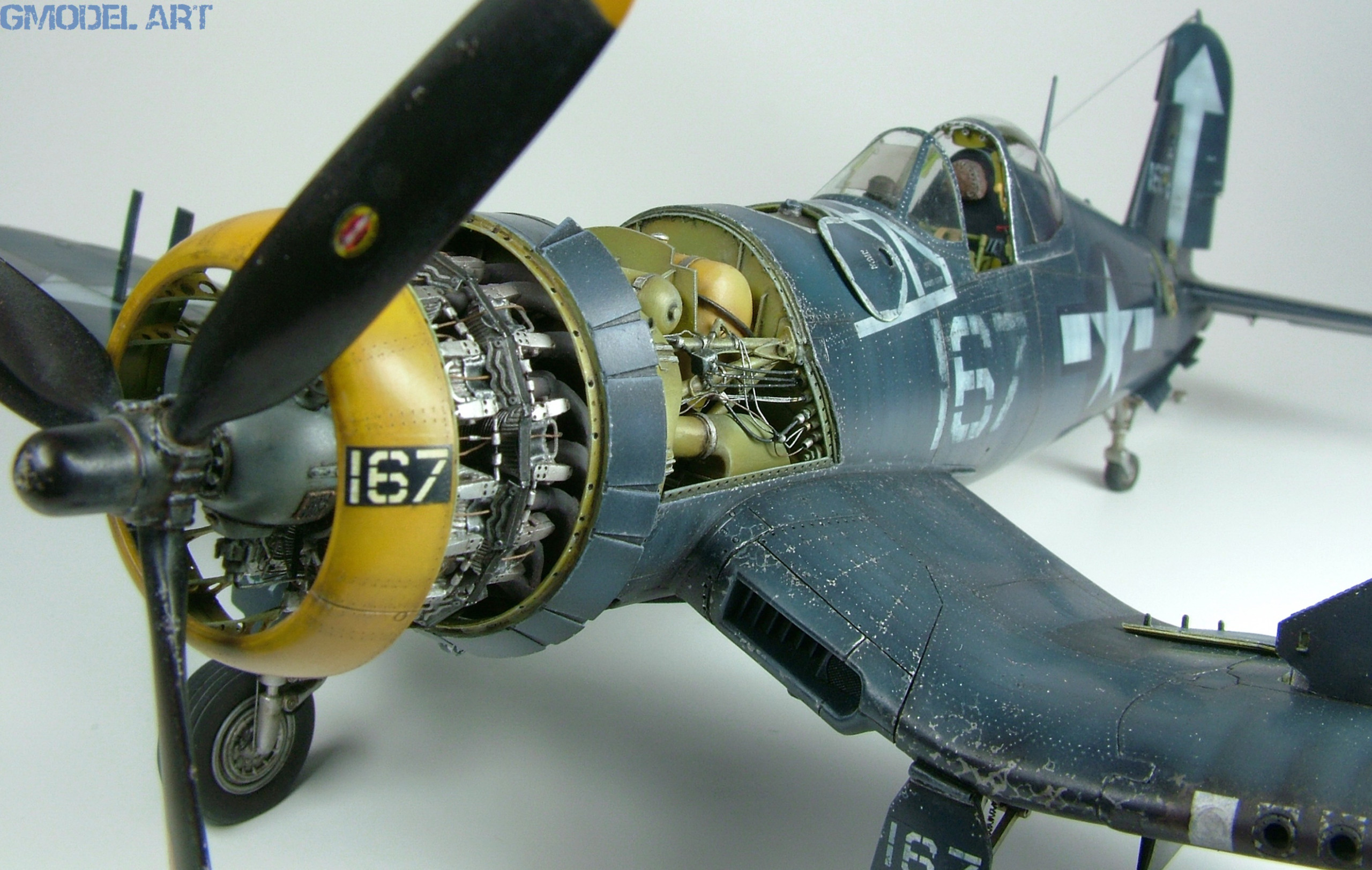
After completely marking the rivets and spot welds, I gradually started to cut the engine covers at the forward portion of the fuselage, fuel tank covers, the rudder and antenna column, inspection panels at the aft portion of the fuselage and on the vertical stabilizer. Of course it is, as usual, imperative to minimize the wall thickness of the fuselage for future installation of the “Aires cockpit and engine”. Next up was to build the upper part of the fuel tank including the fueling nozzle and seal, new fuel and inspection panels, aft fuselage diaphragms attached to the rear undercarriage and other details.
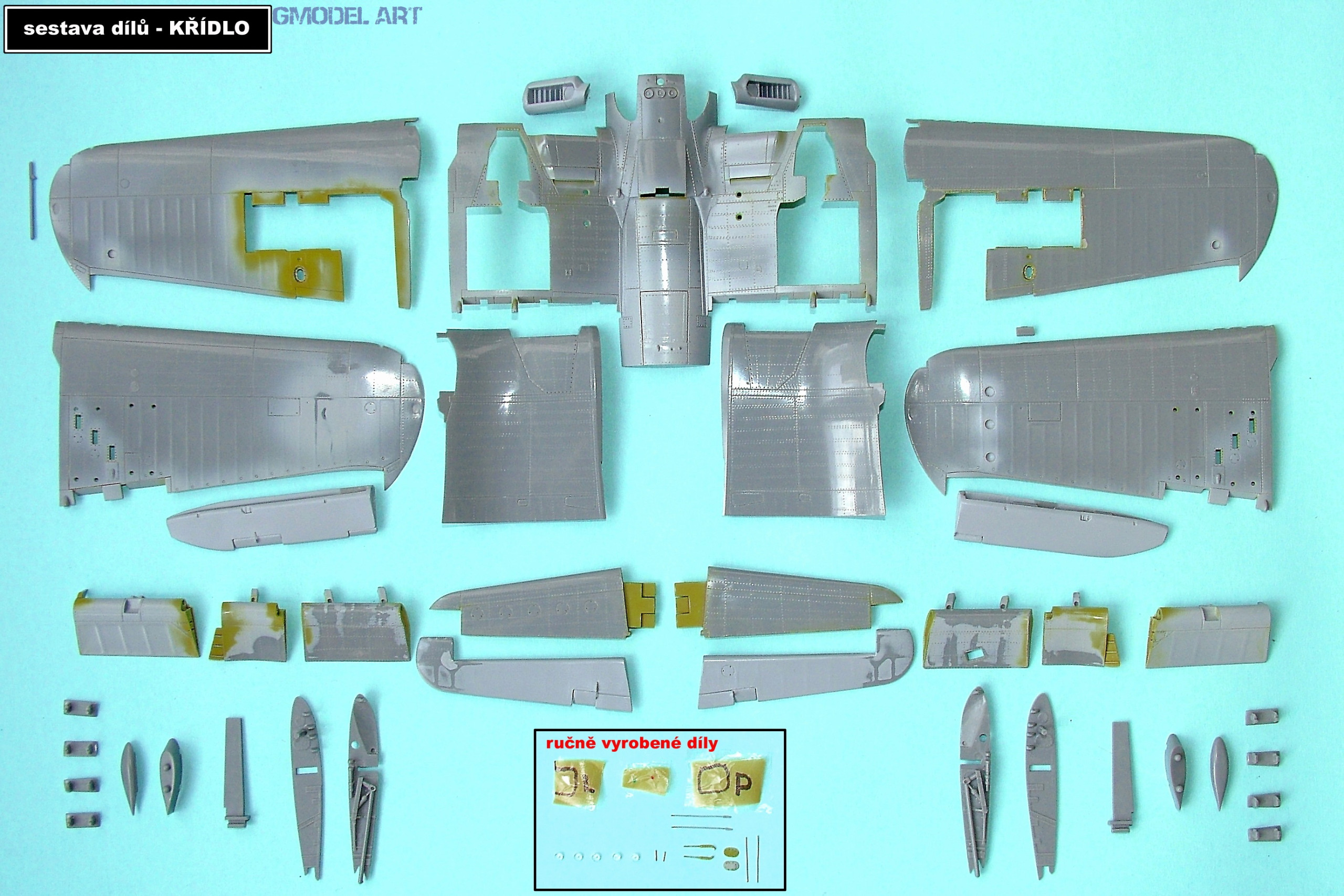
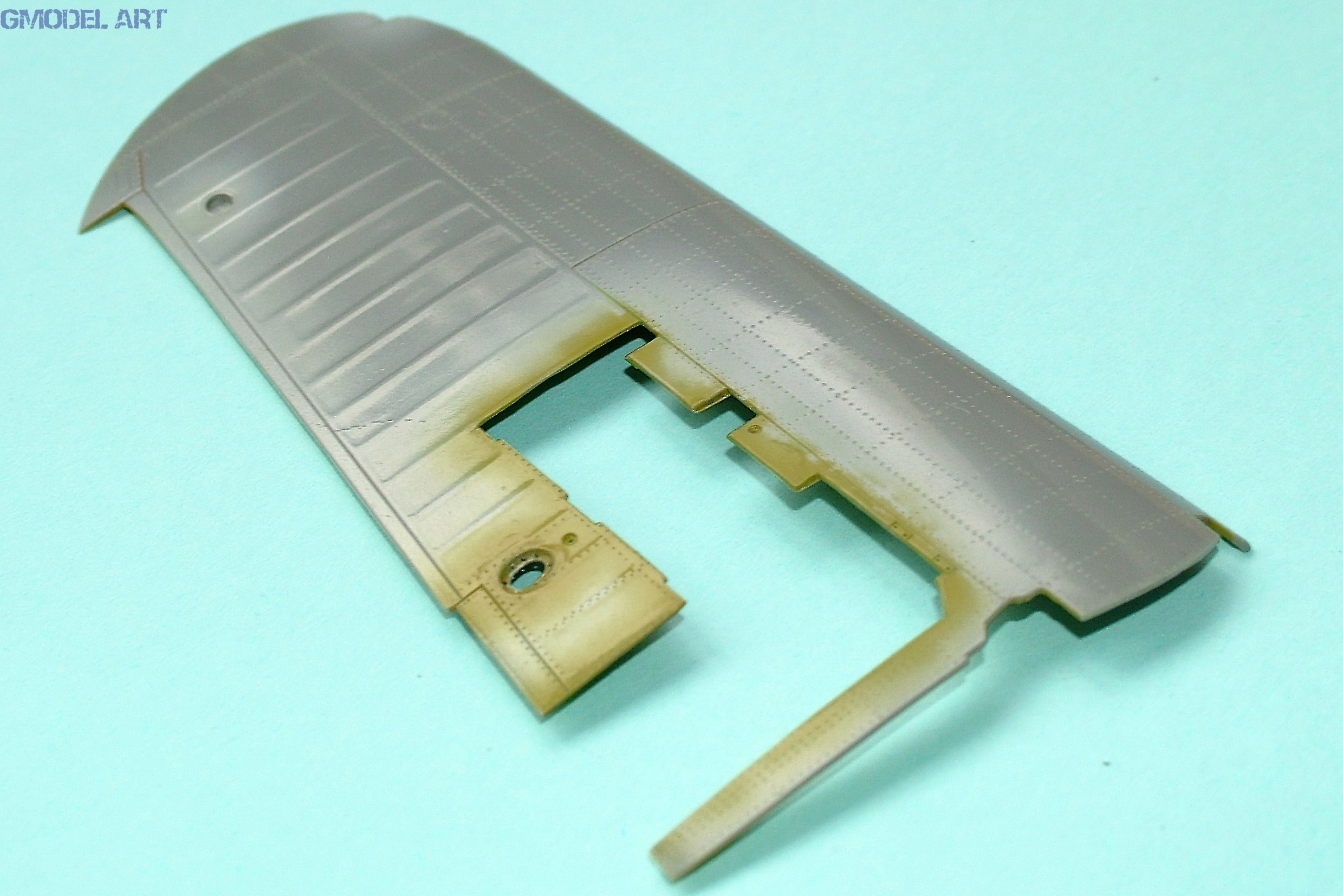
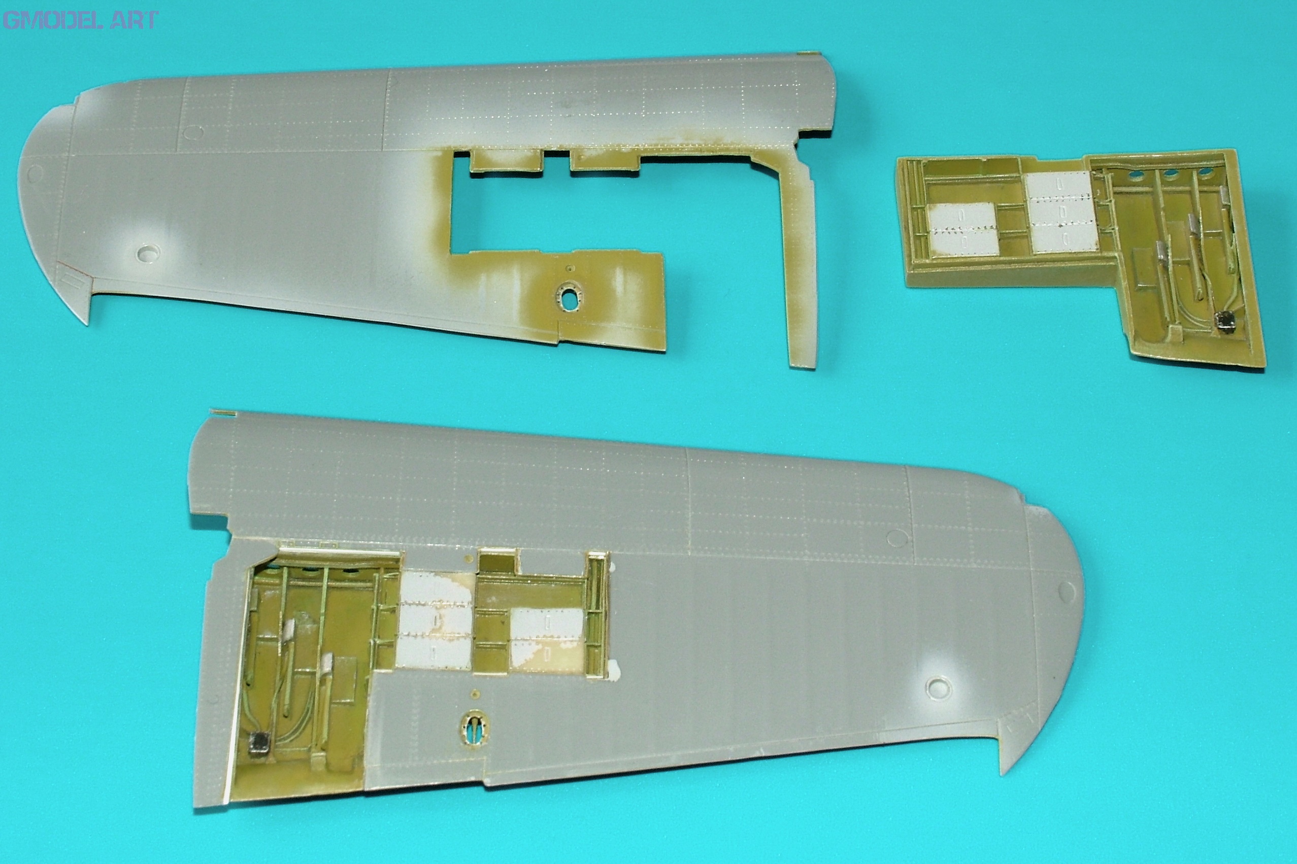
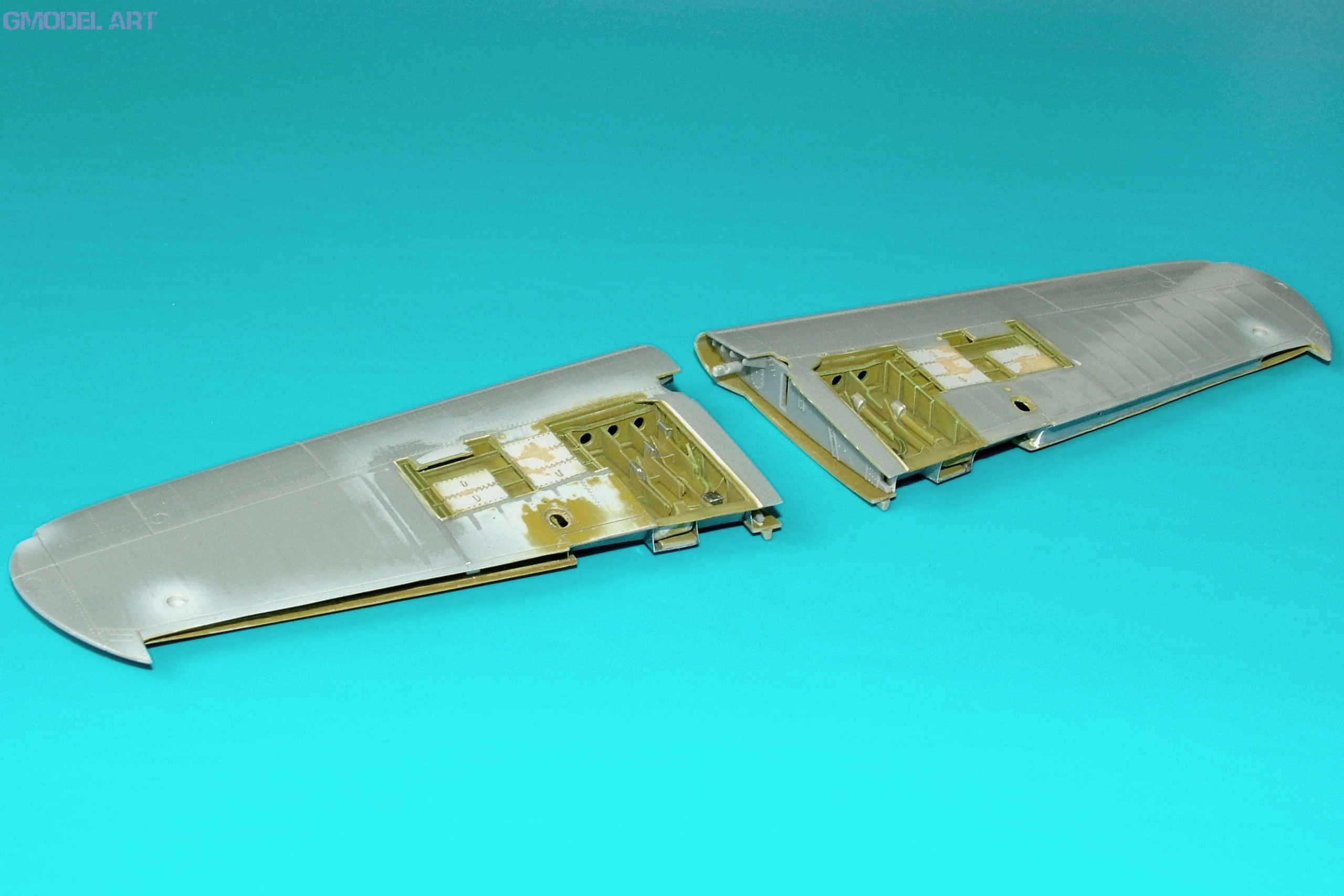
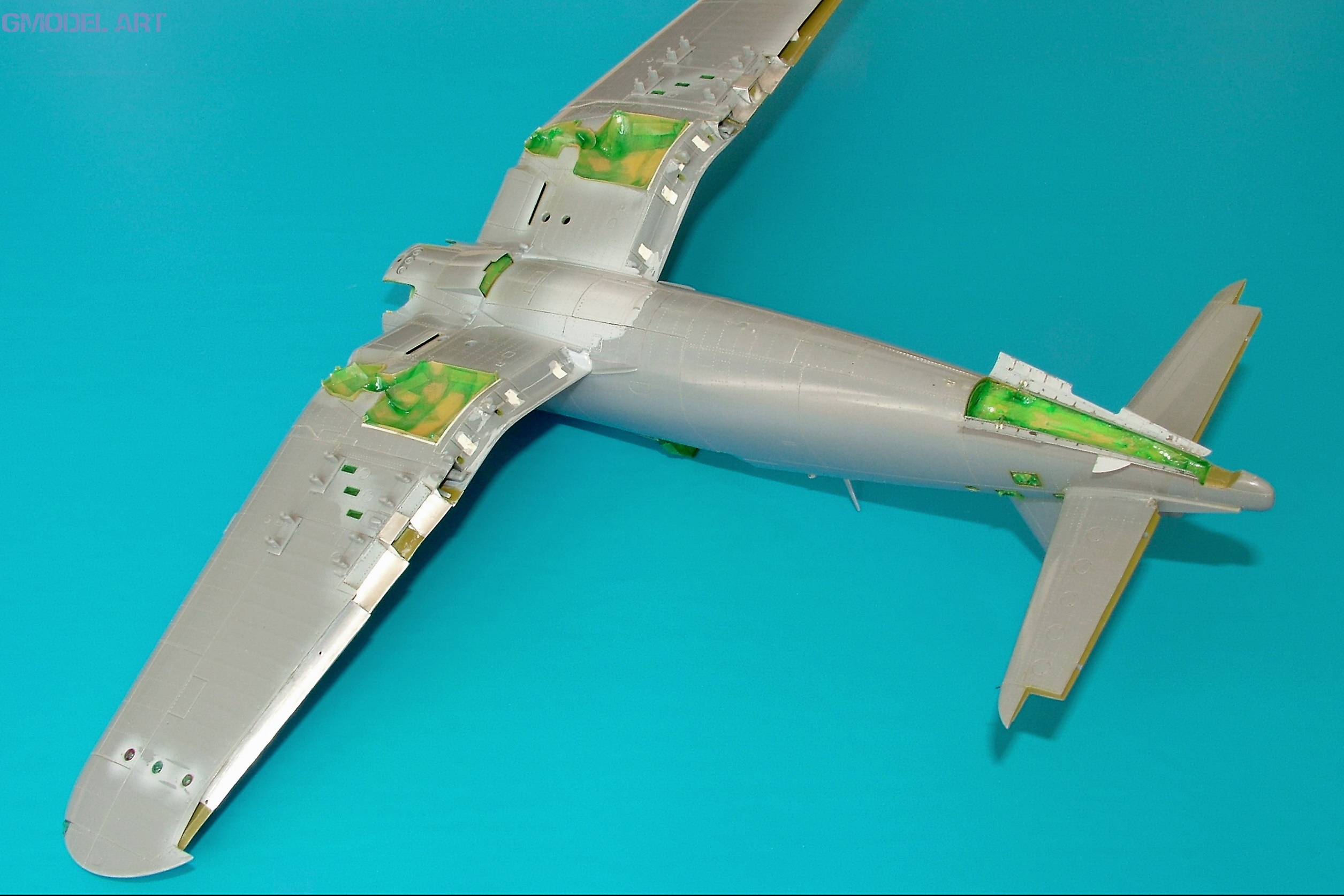
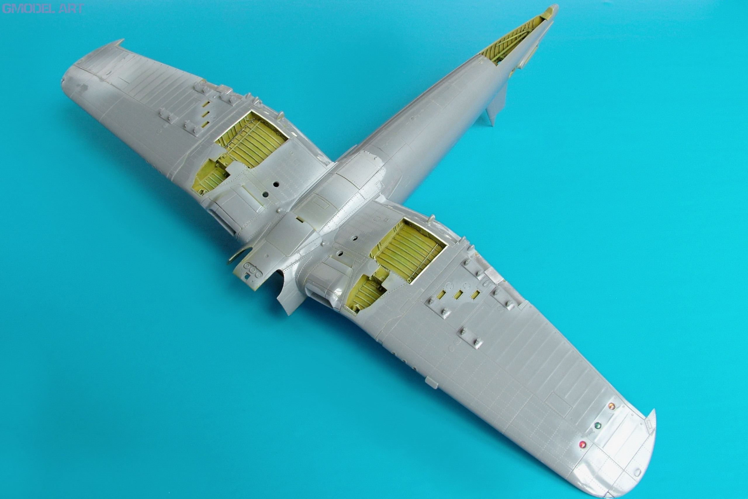
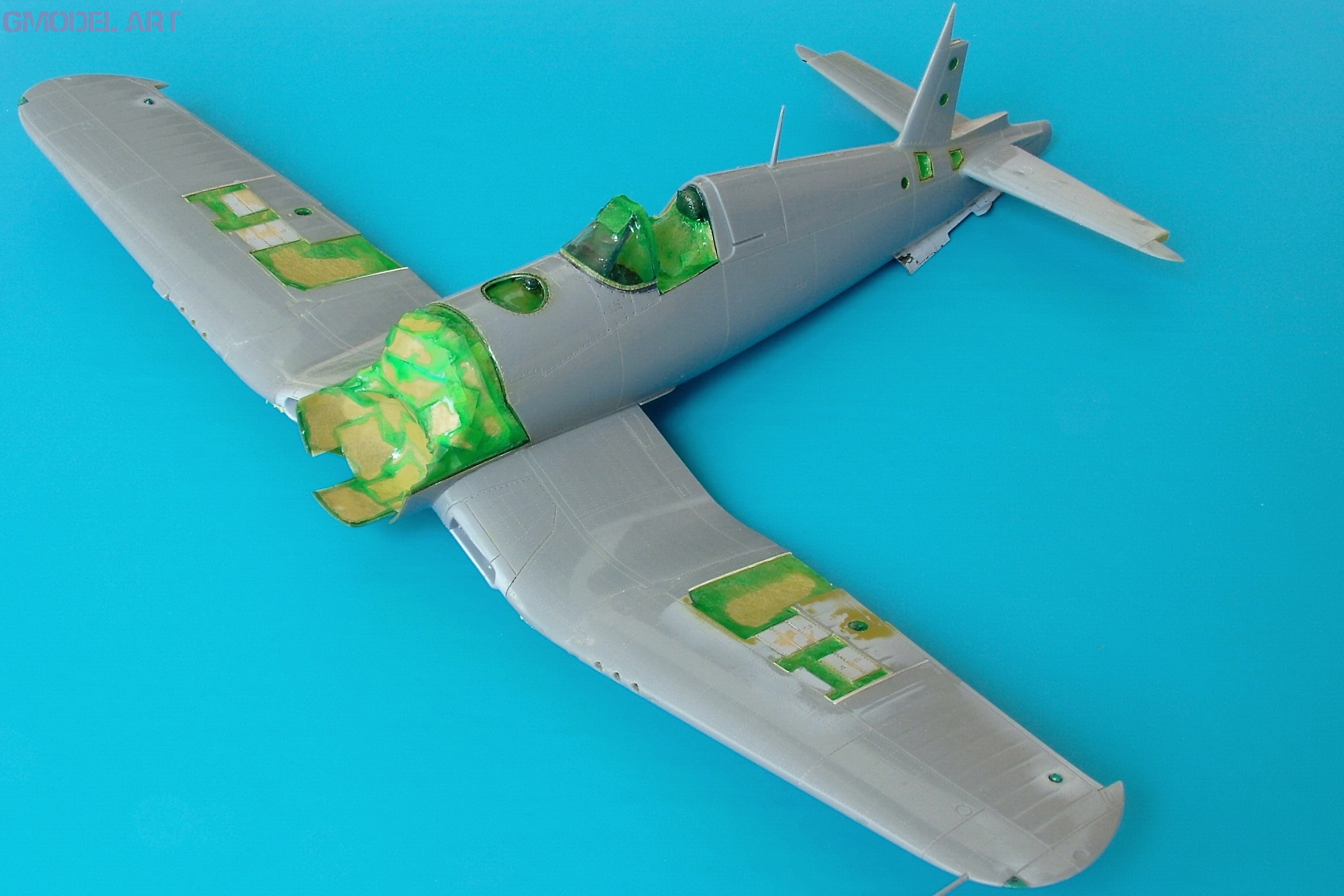
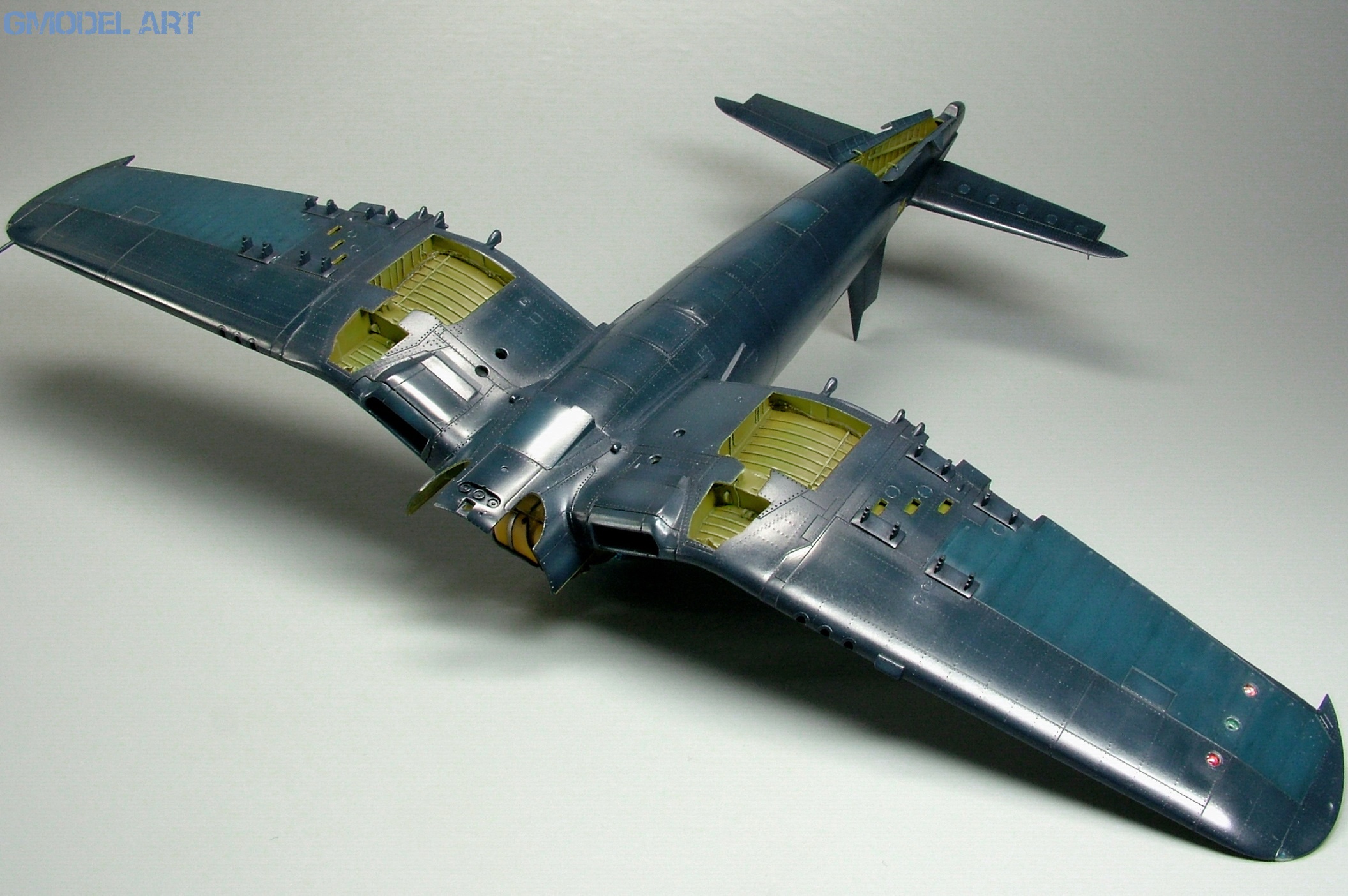
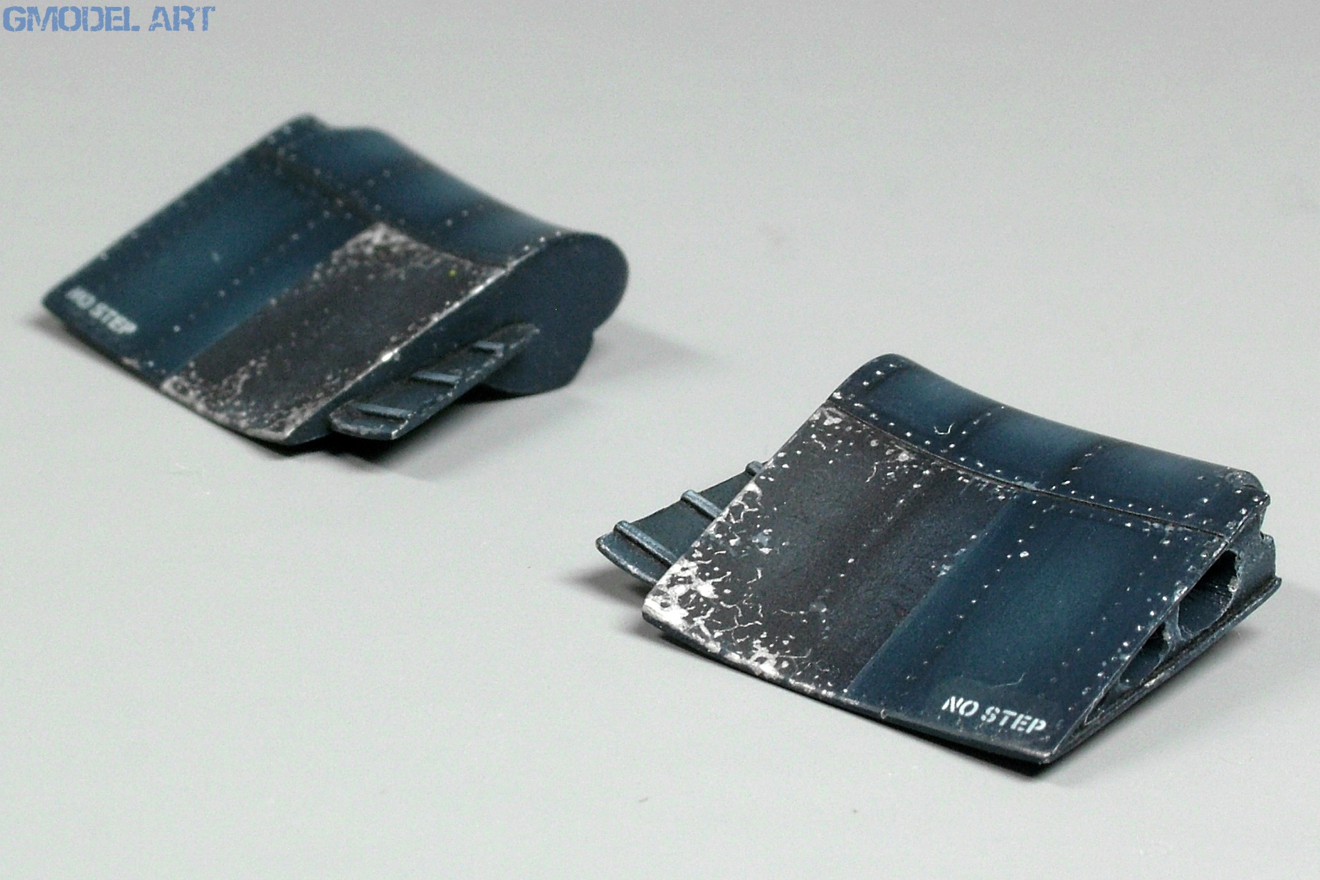
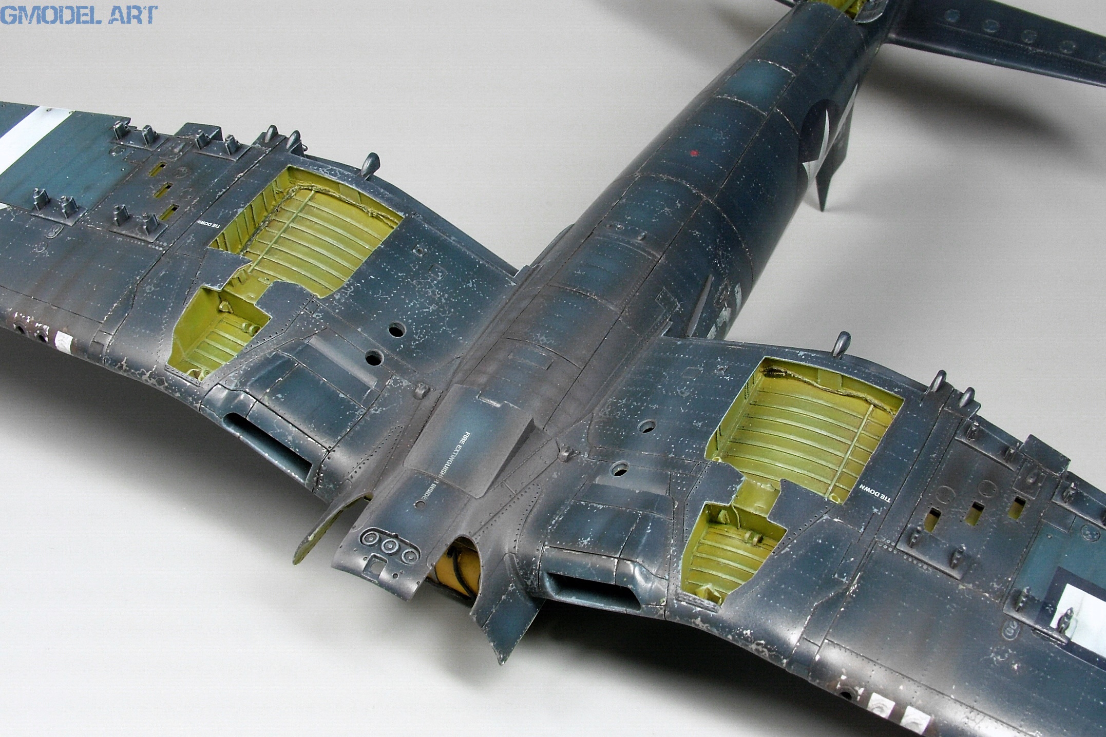
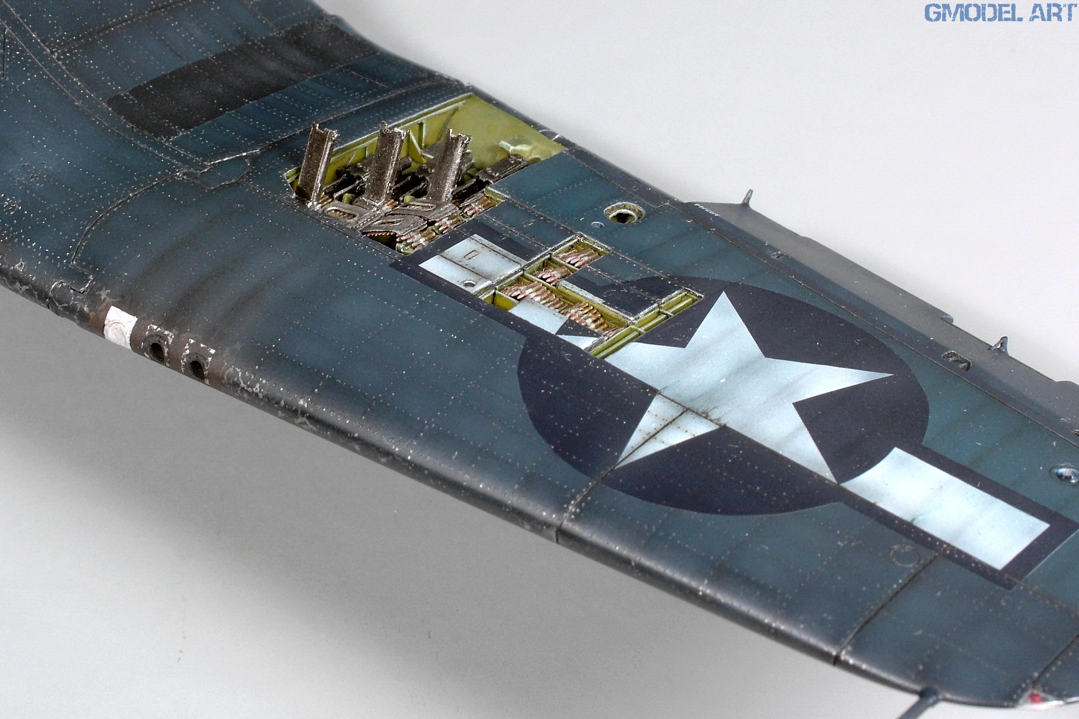
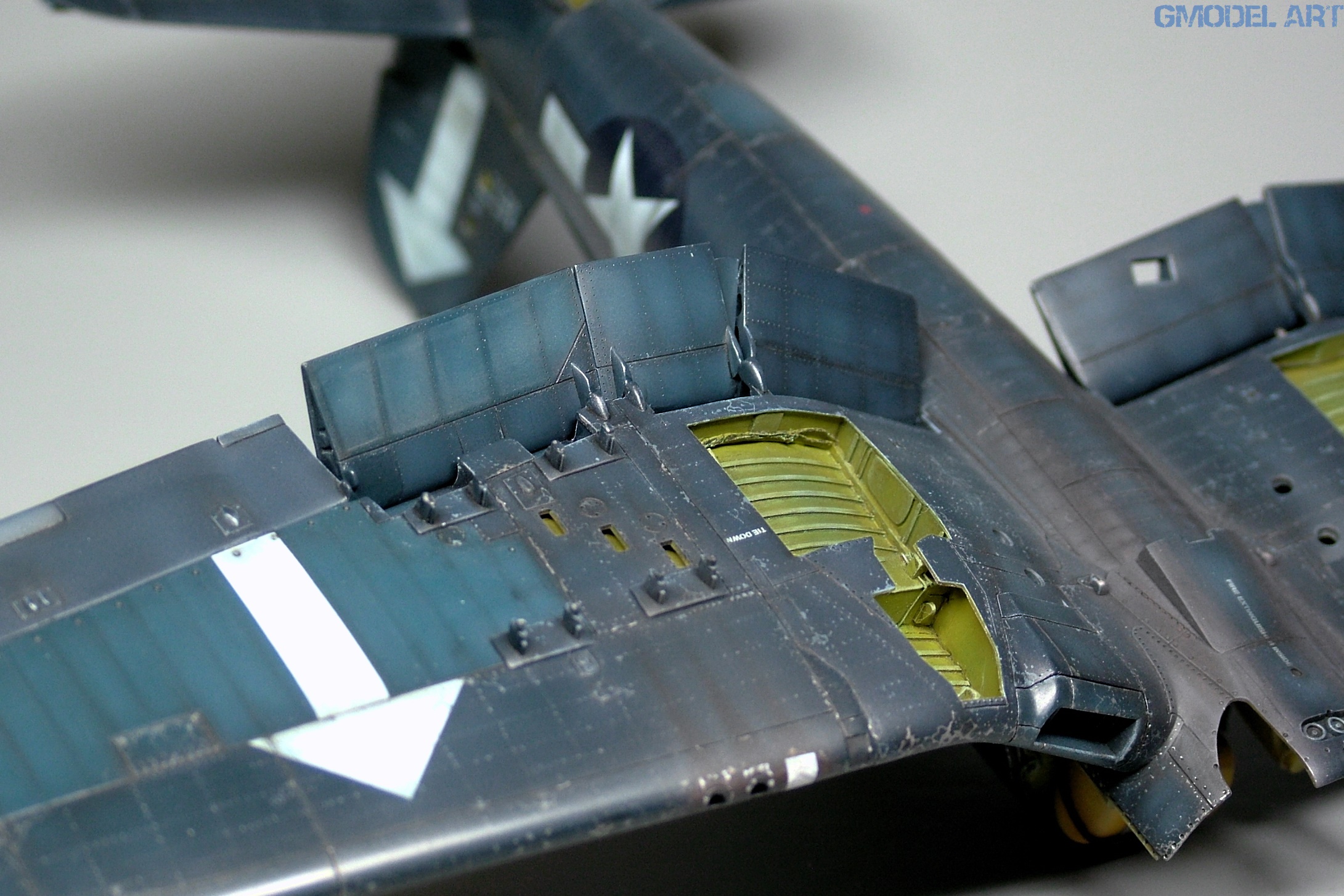
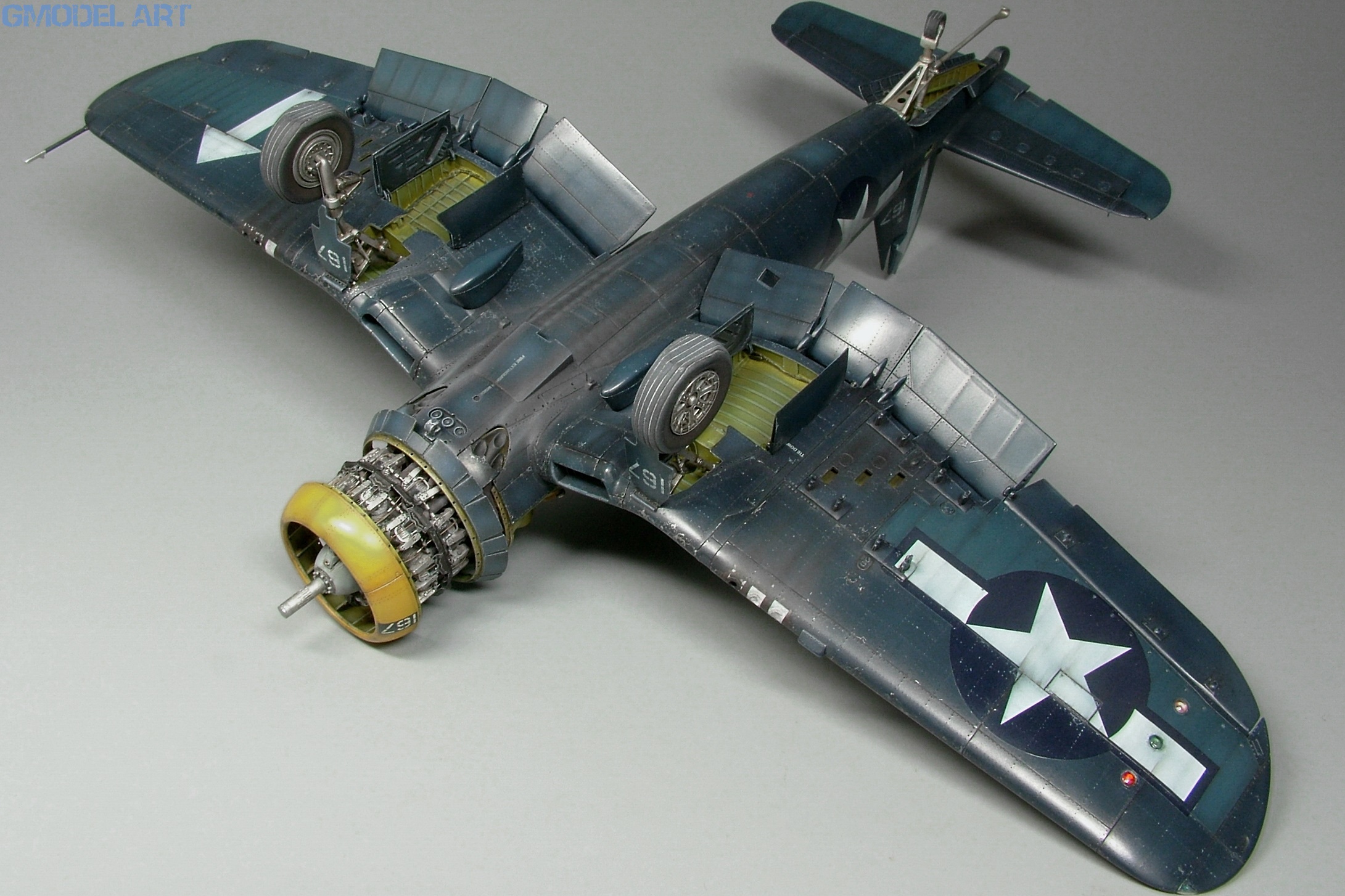
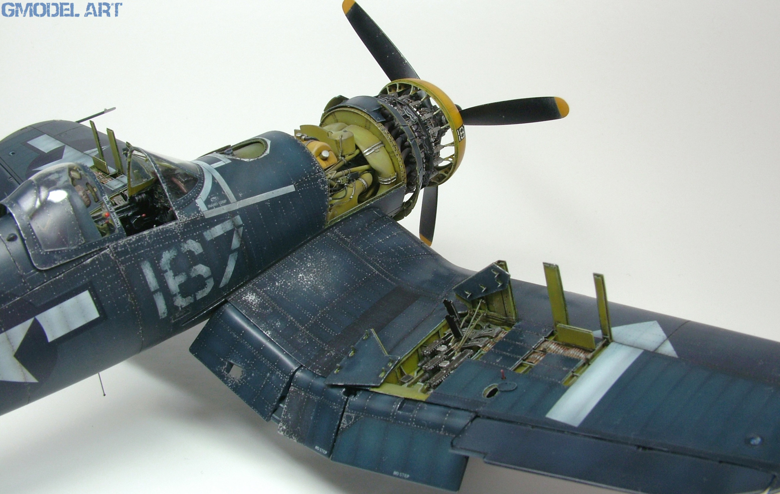
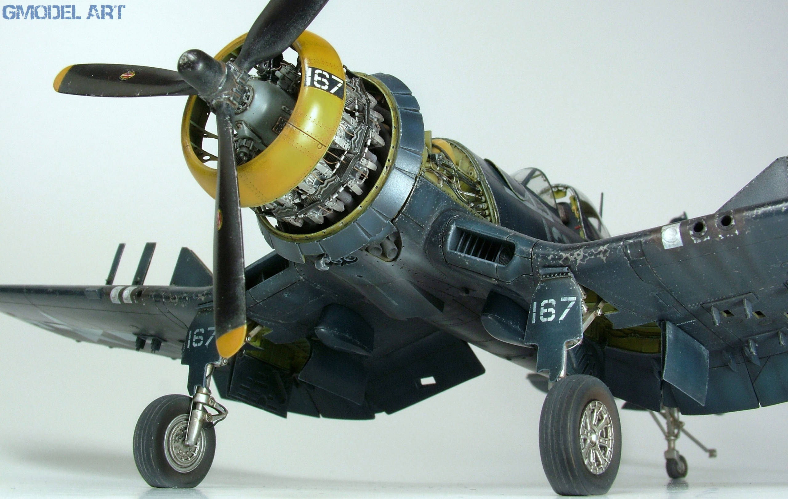
2. Wing Surfaces:
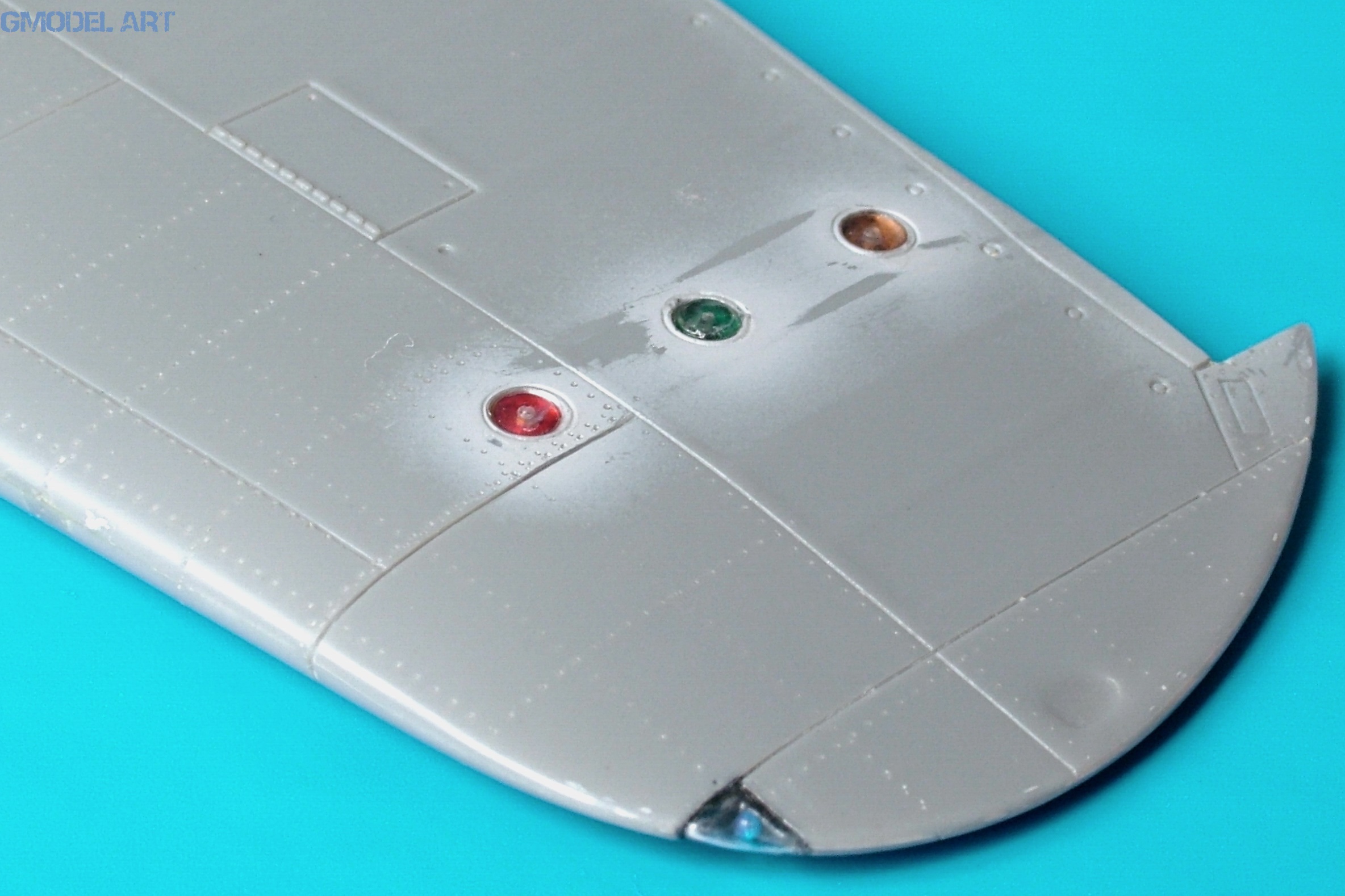
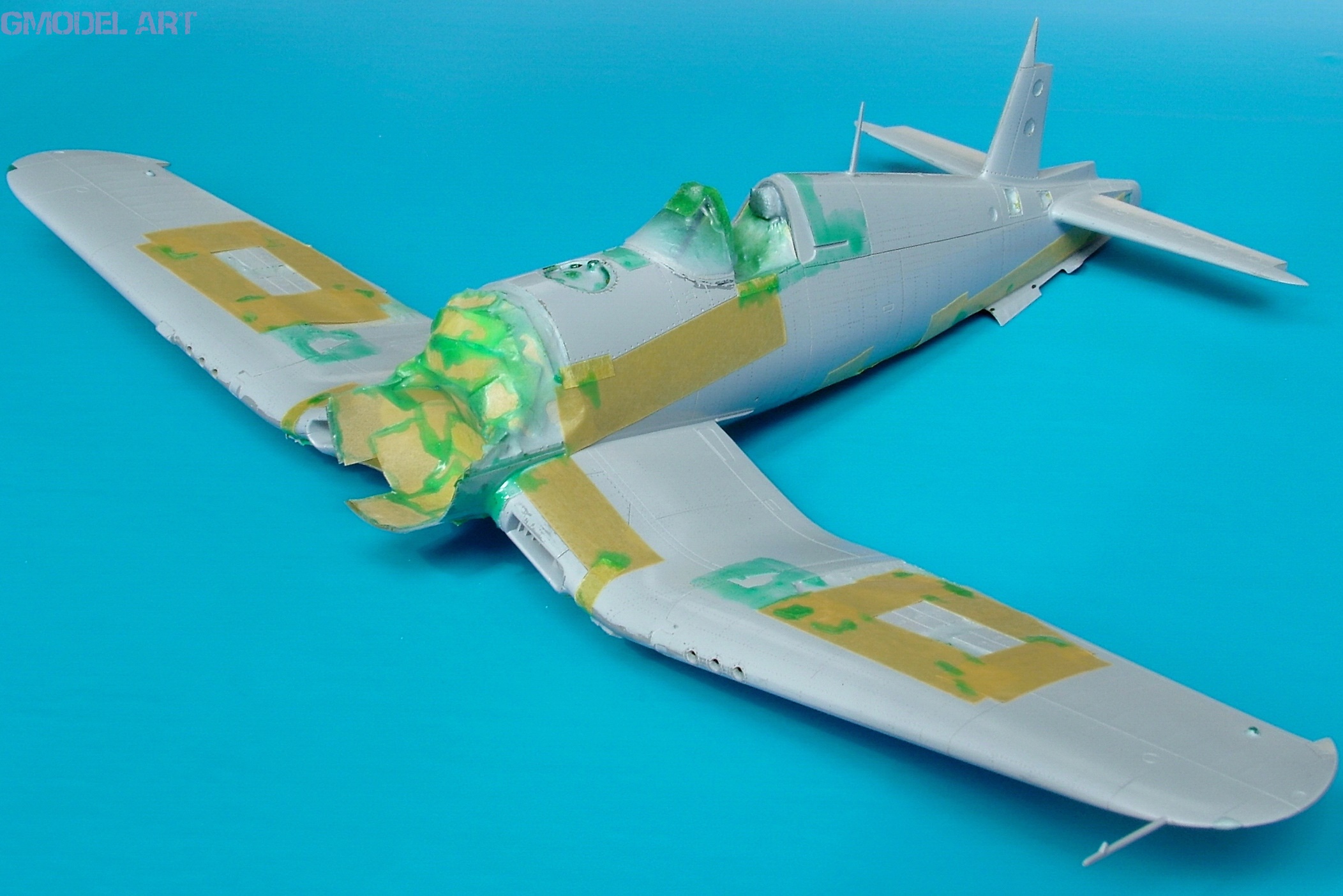
The Corsair’s typical inverted gull wing in a “W” shape, with its folded three piece flaps on each side, is somewhat complex as far as the amount of parts in the kit, its maintenance and the correct geometry during subsequent assembly completion. As on the fuselage, the whole wing and portions of the tail surfaces were “re-riveted”. I then went into cutting and adjusting the wings, elevator, balancing surfaces, position, identification and formation lights, not very model-like exhaust tips and other bits and pieces. Following was a series of cutting the main landing gear shafts, all weapon pit covers and once again minimizing the wall thickness for additional set installations.
Worth mentioning is the use of transparent colored “lights” from CMK as position lights with a hand-made tweak by overlaying it with a clear acetate foil which I, after heating, shaped and fitted over the end curves (wing tip).
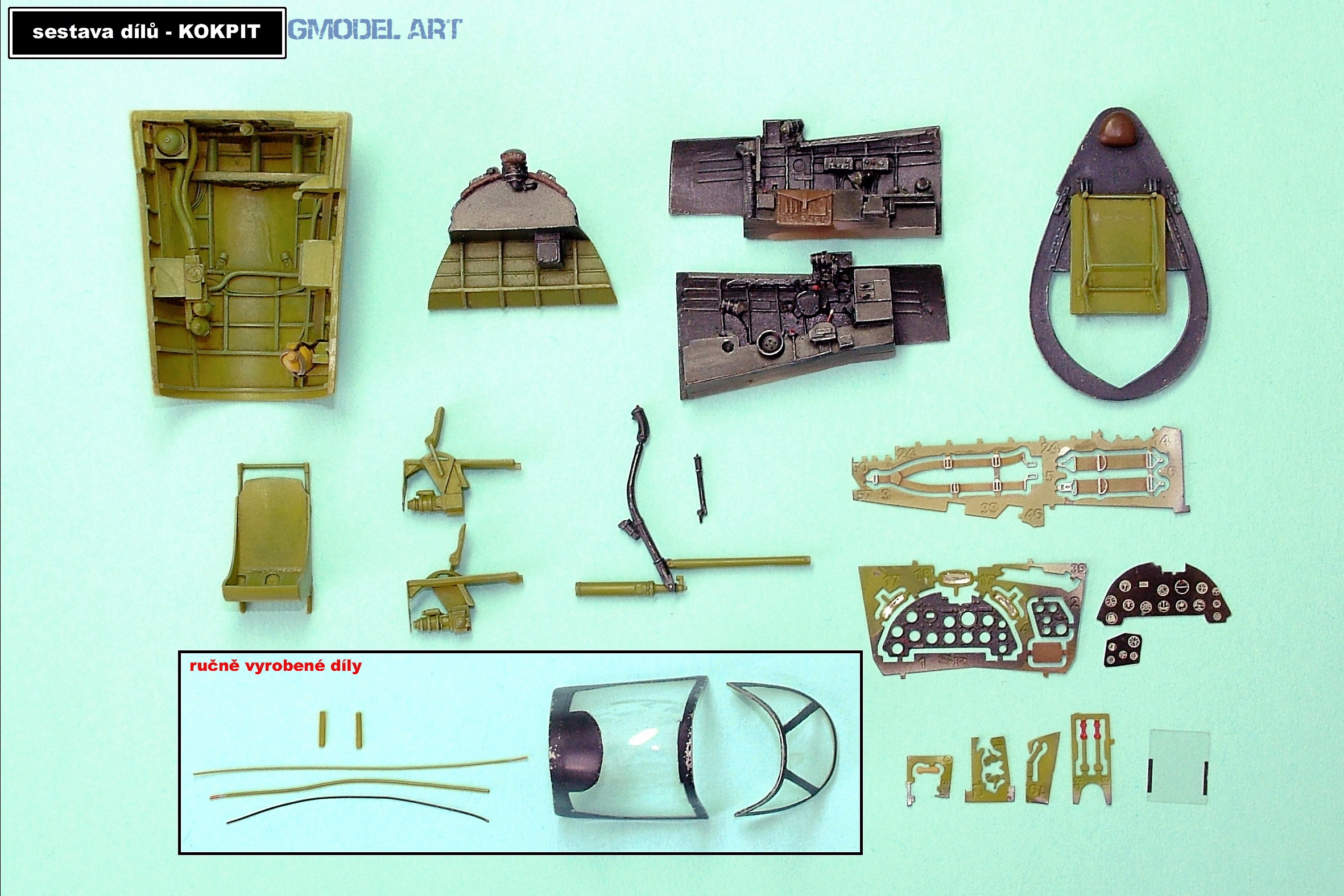
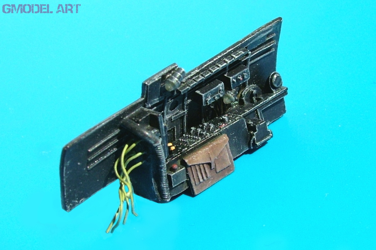
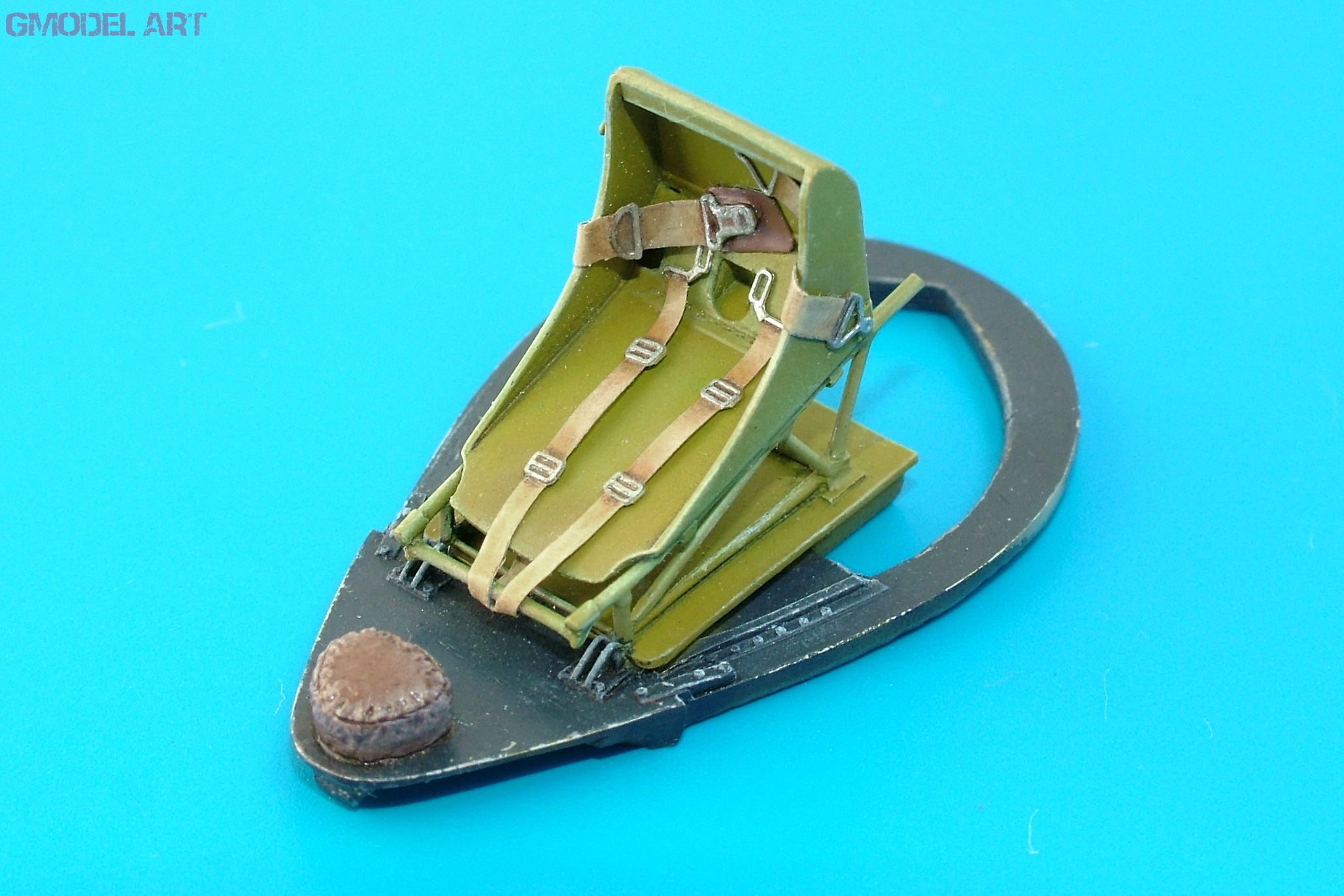
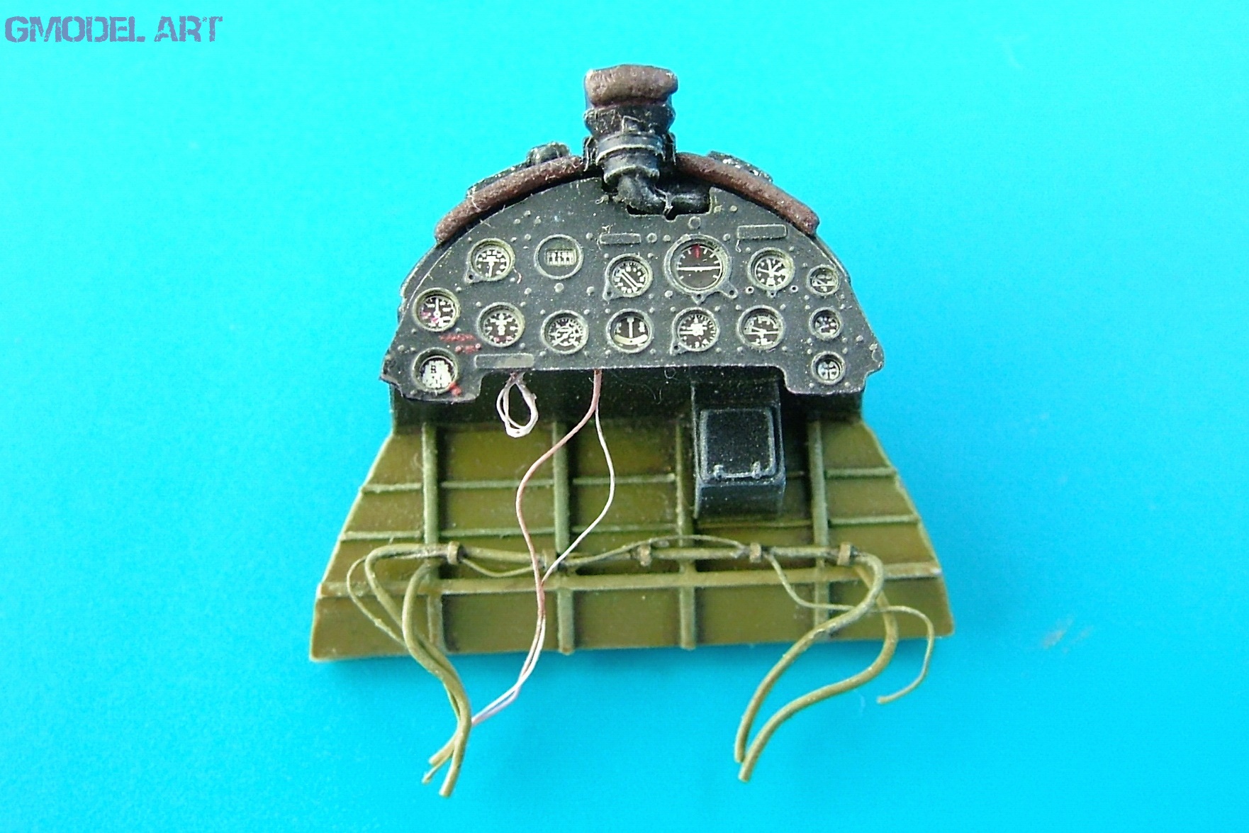
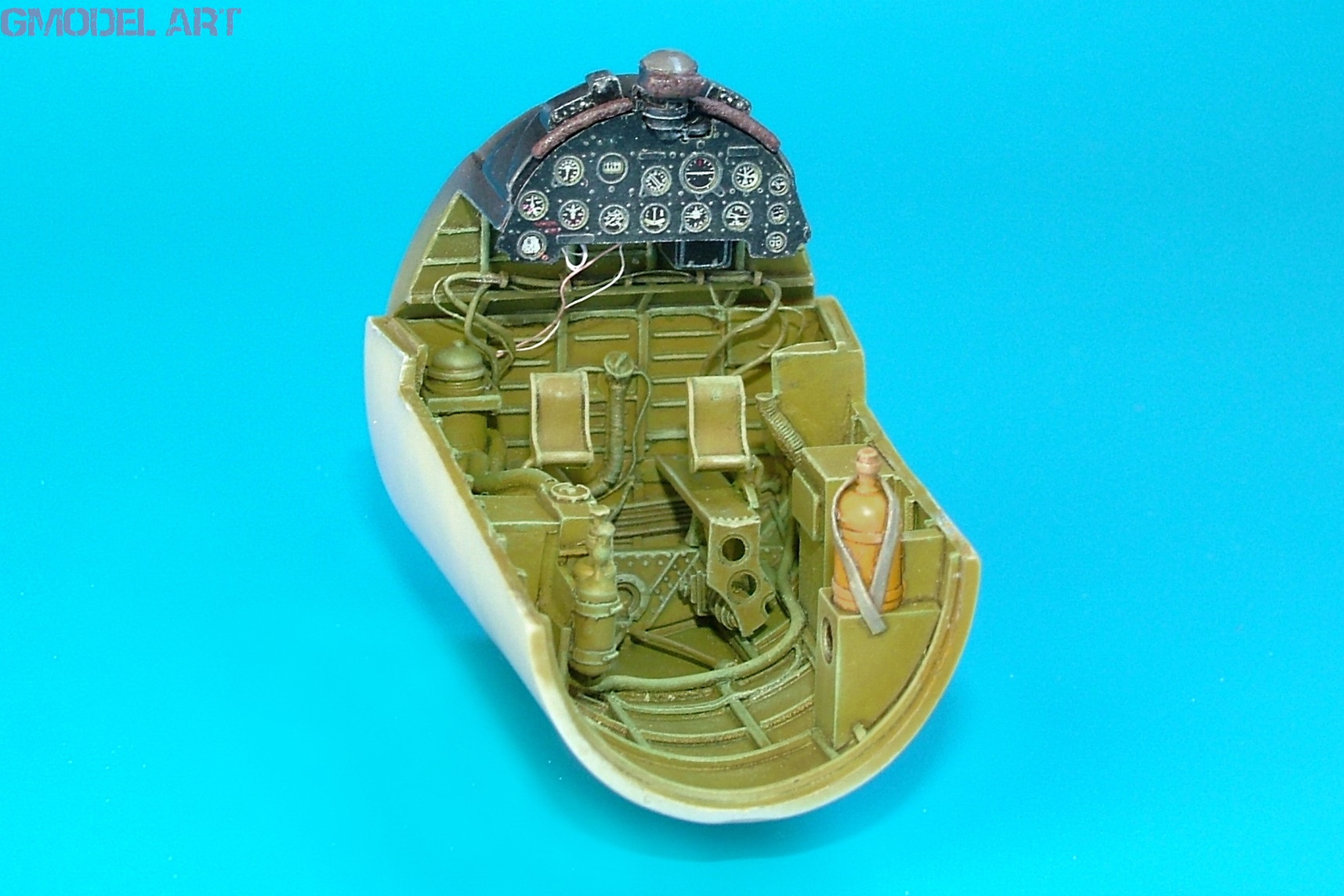
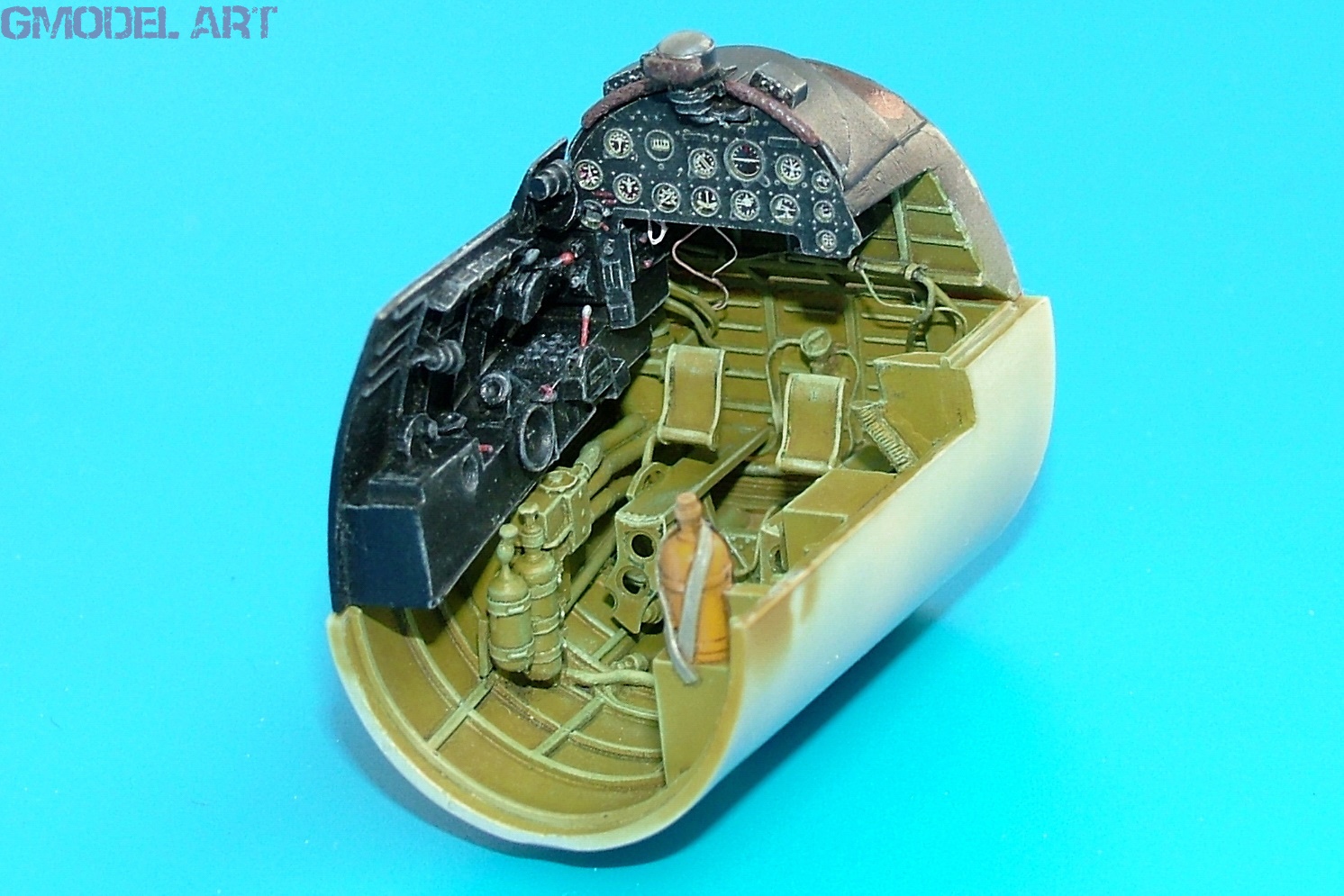
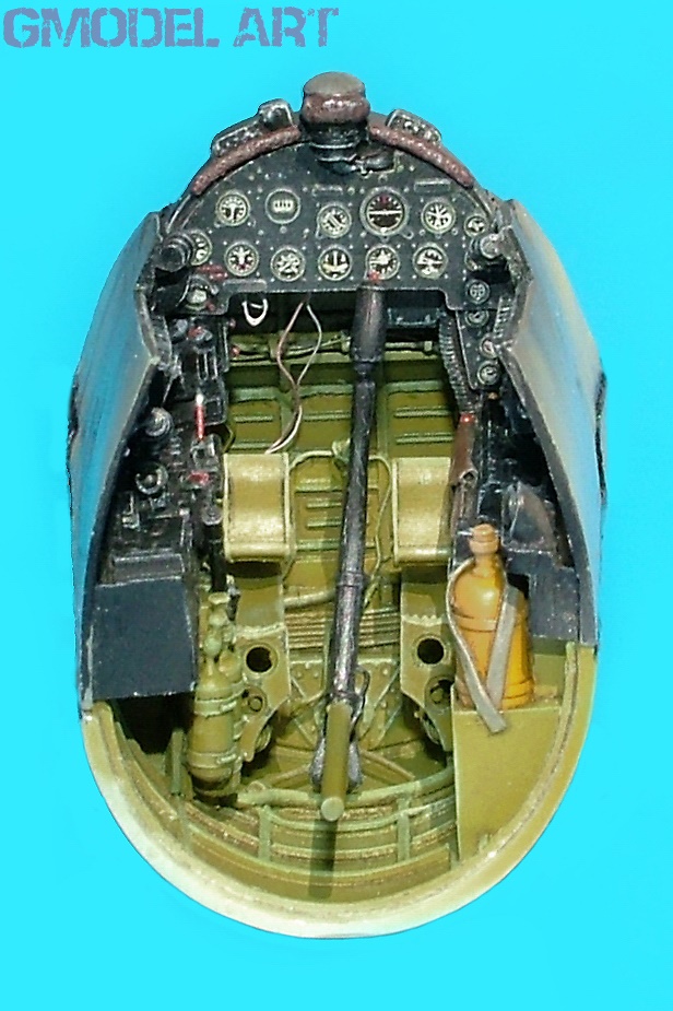
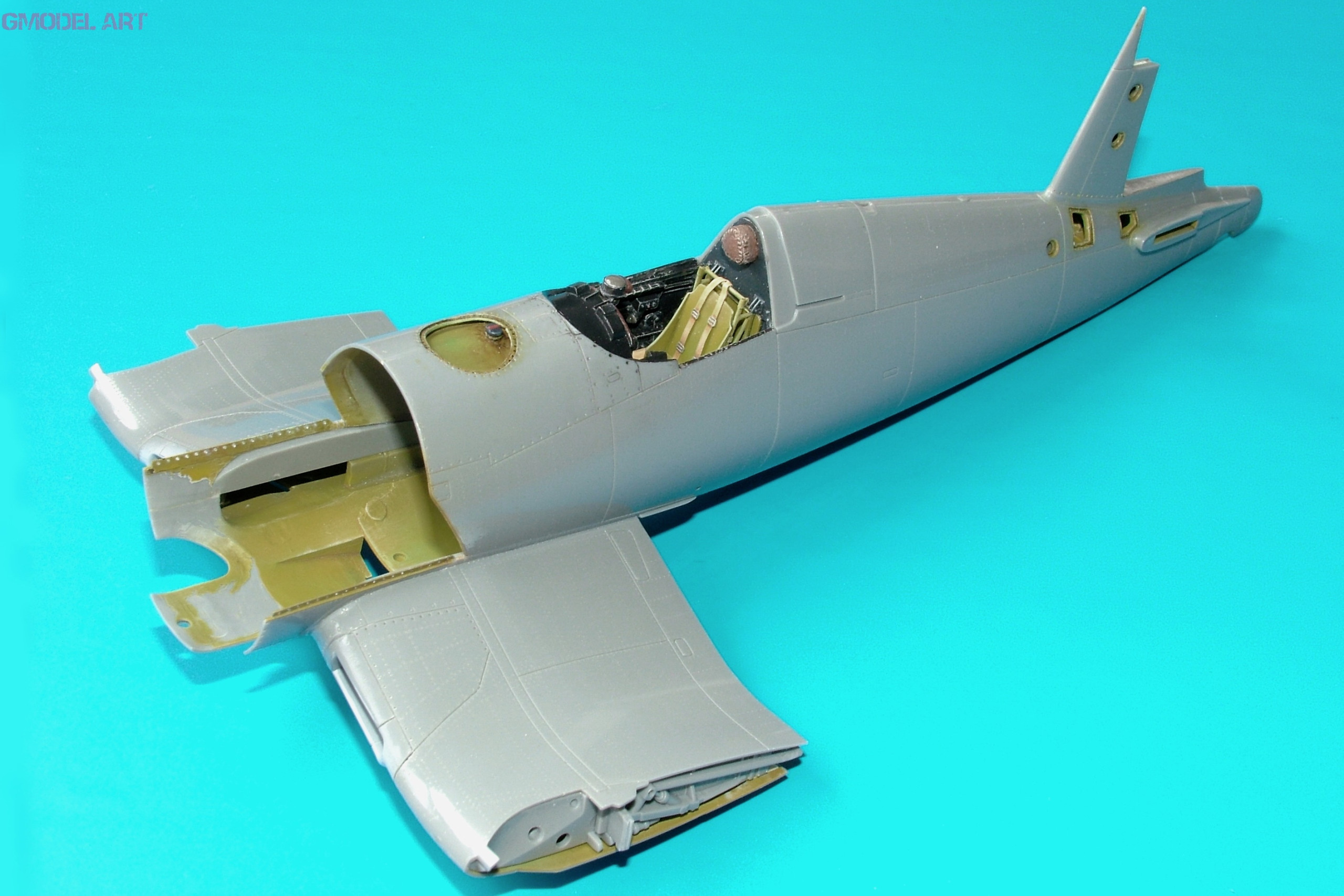
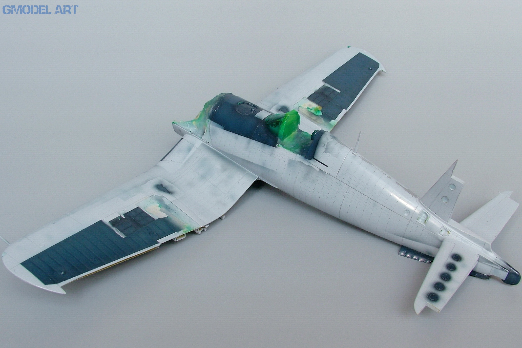
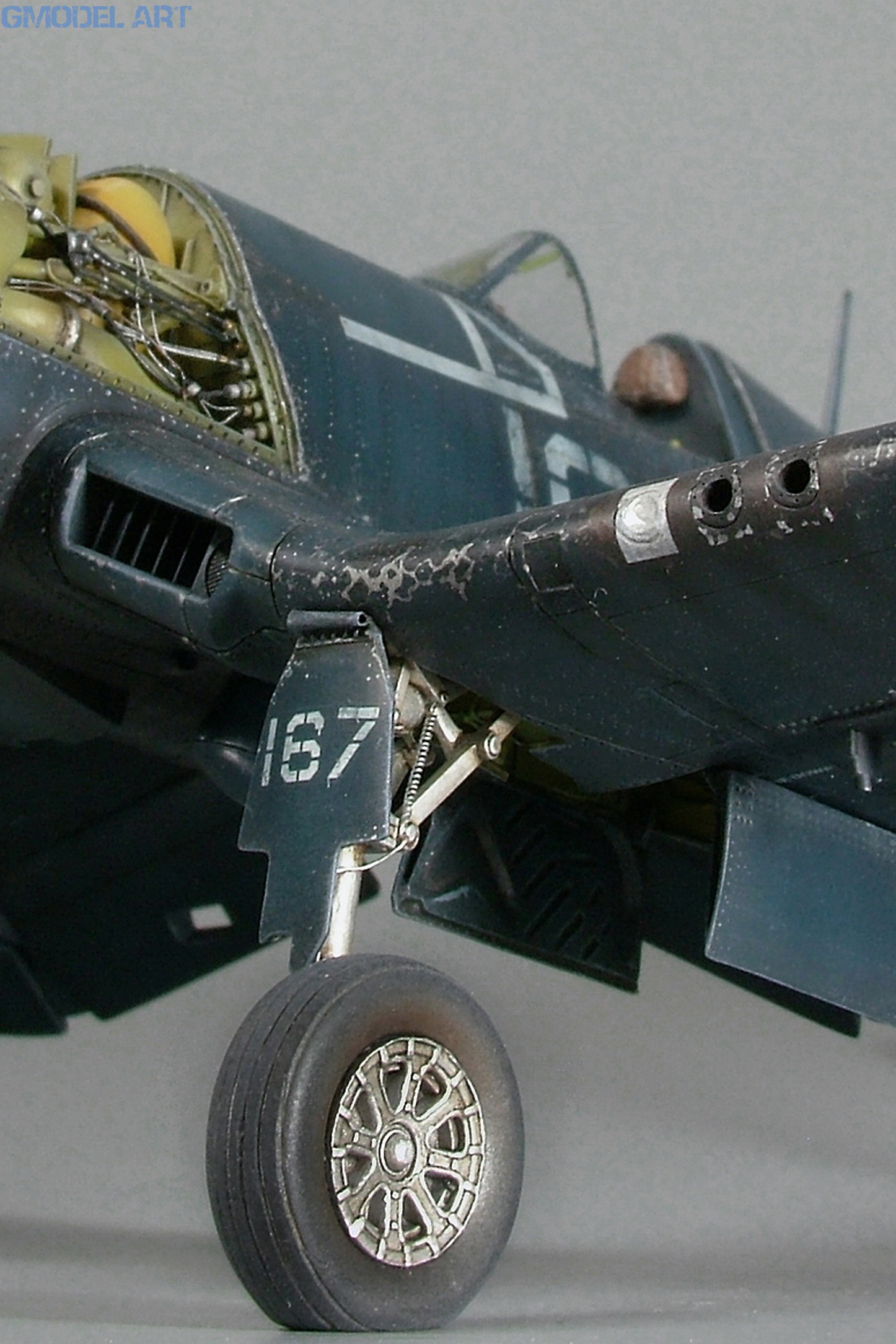
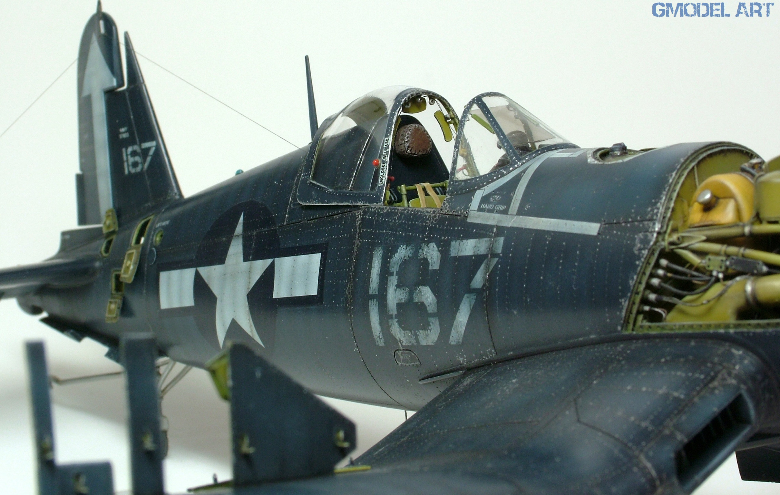
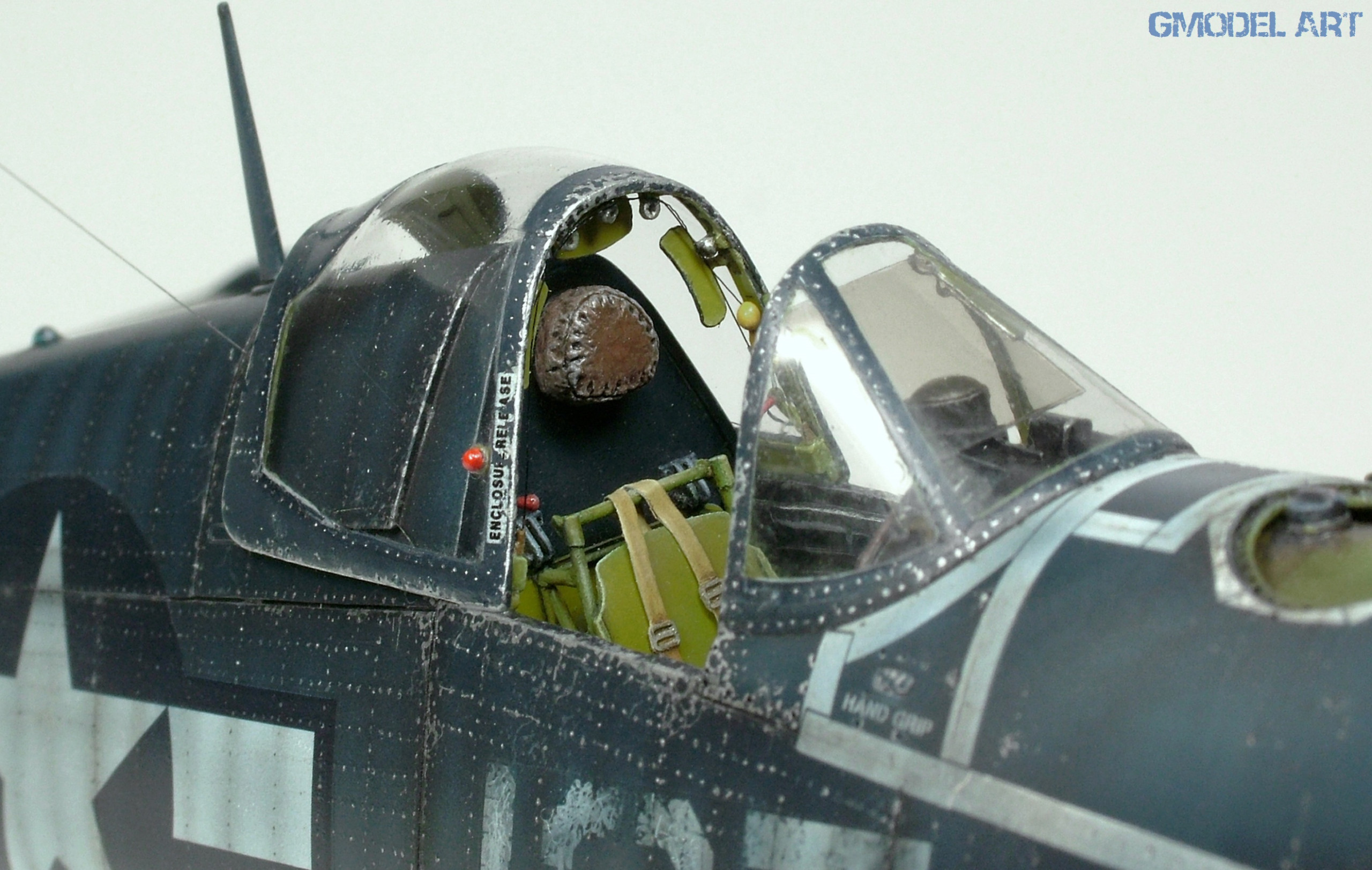
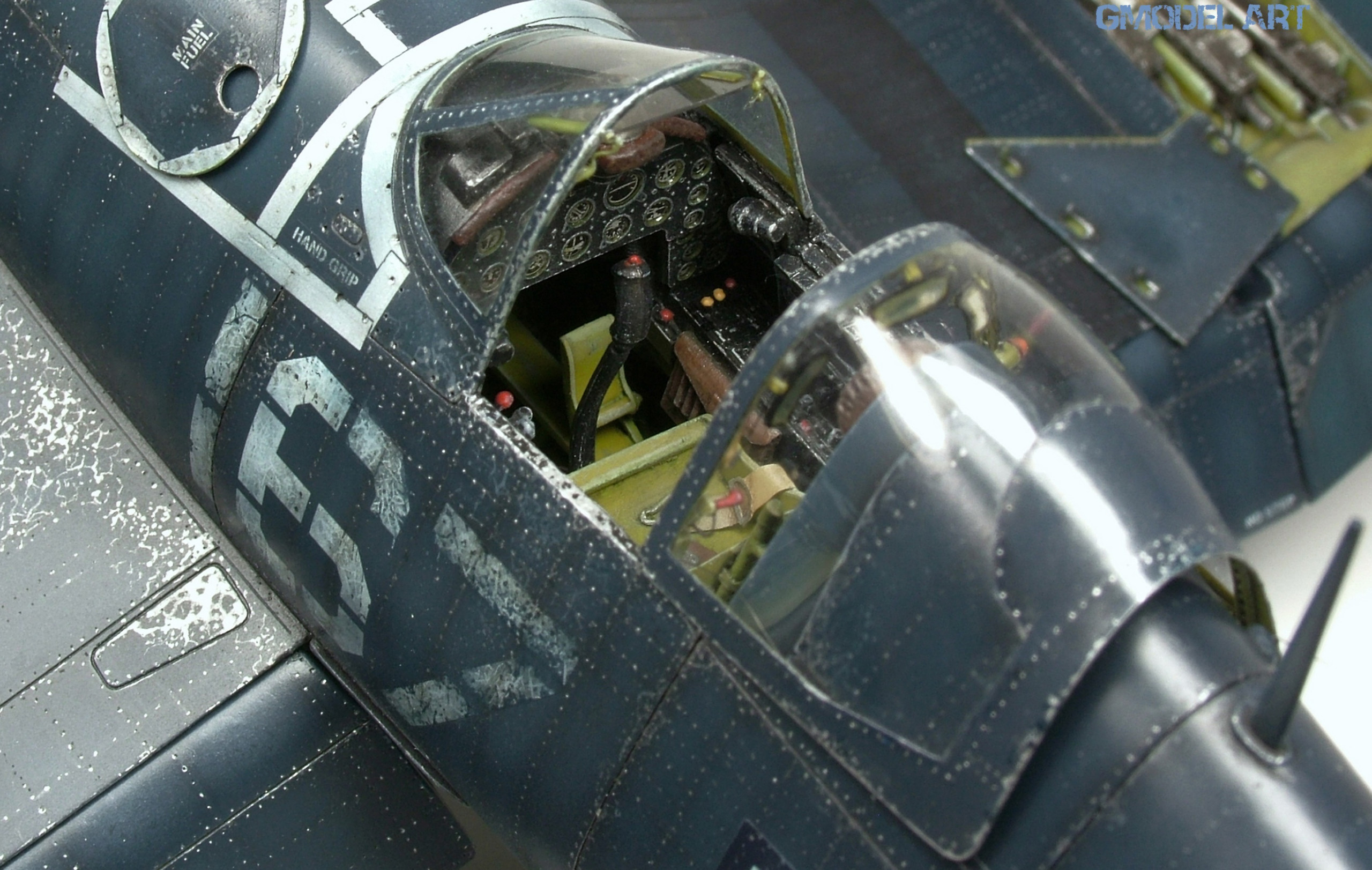
3. Cockpit:
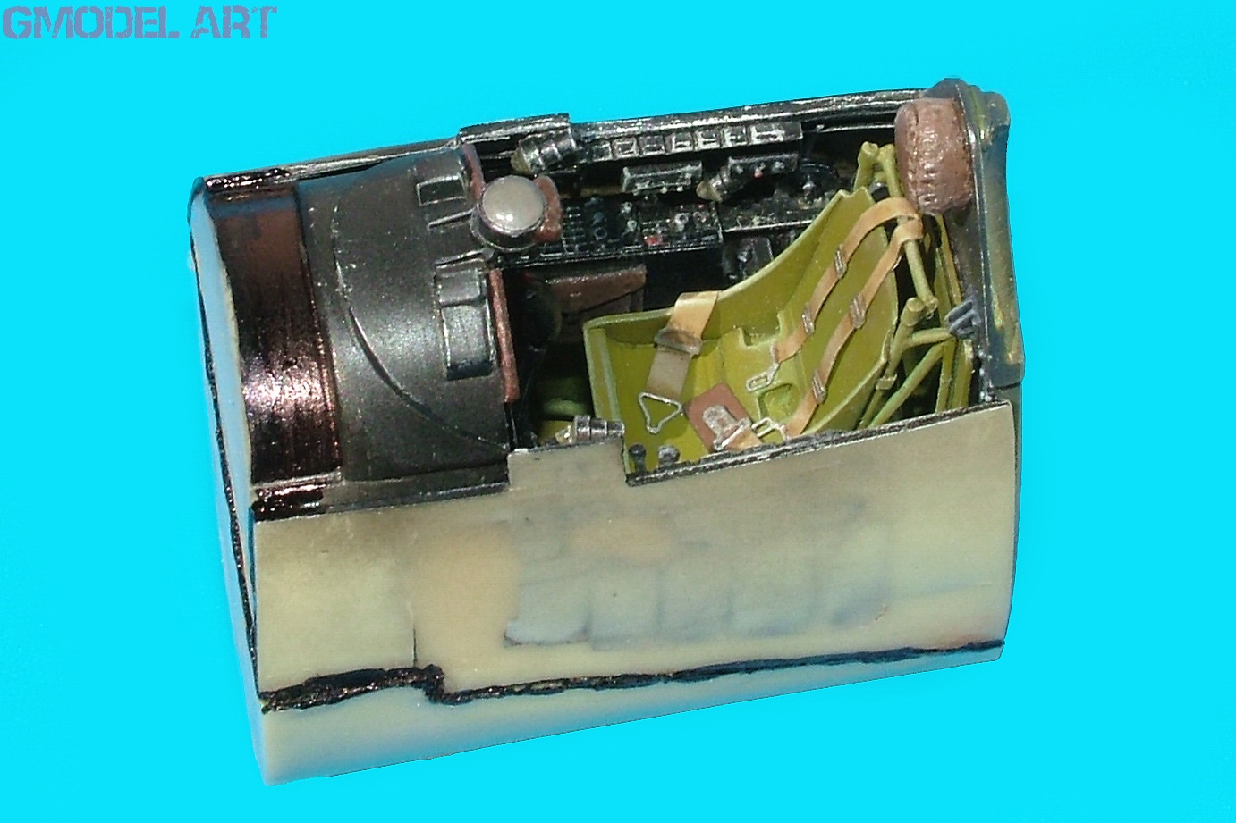
The “Aires” cockpit is of first class trade and fully replaces the original pieces of the assembly kit. All that is remaining are some minor details like the cable system, levers, light bulbs, imitation leather upholstery and also once again, carefully minimize the wall thickness to the width of paper.
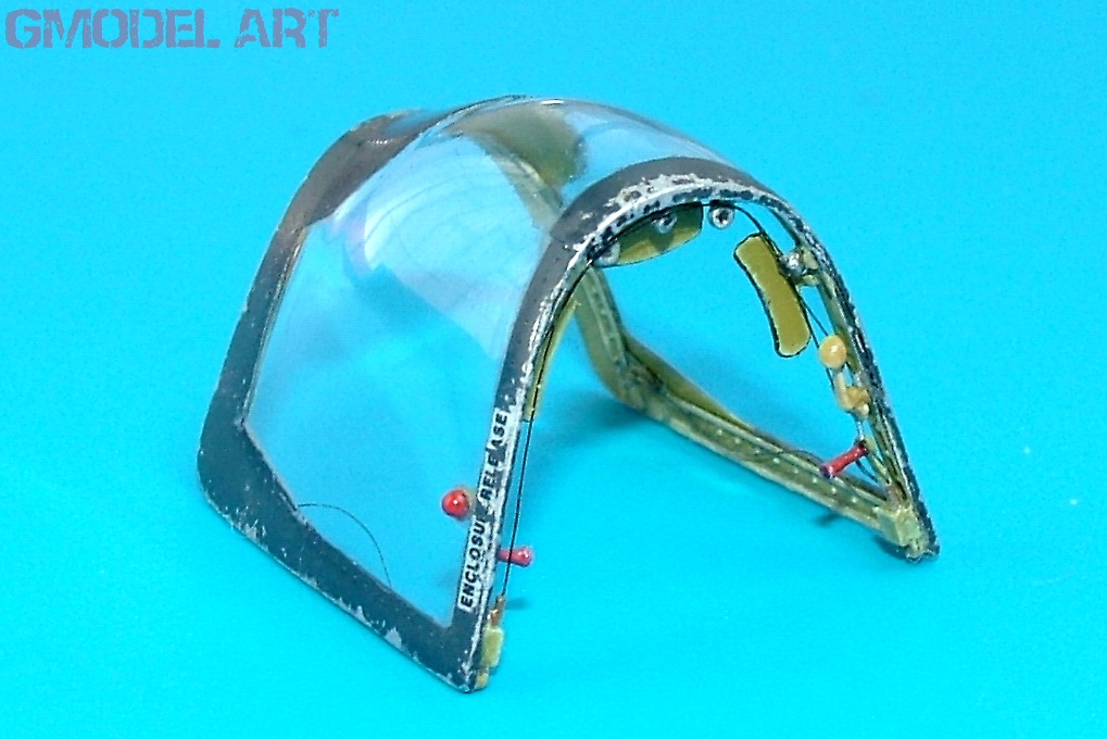
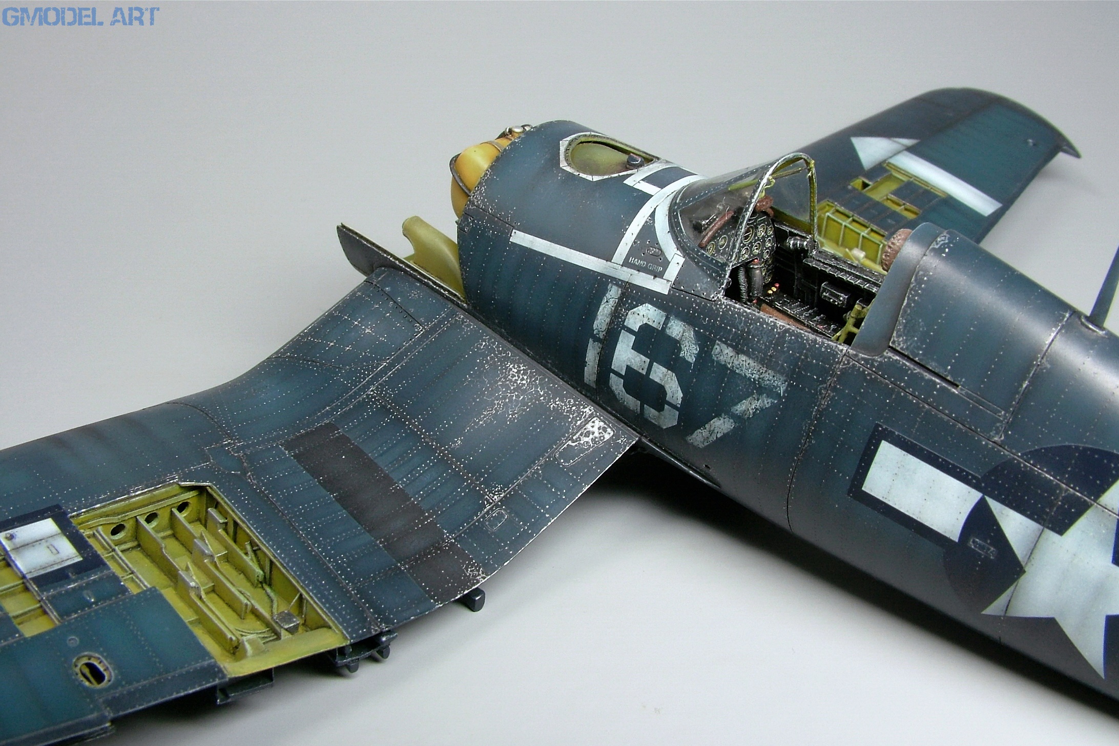
Construction of the cabin cover is its own chapter that consists of two parts; a solid front armor and movable aft parts. Both parts of cabin I created with the help of clear acetate foil which I after heating, shaped and fitted over the original cabin from kit. It was also necessary to work out the interior constructions of the cabin. Casts from the Aires kit were available for use on the movable parts but for the front part of the cabin I had to create and rivet a hand-made aluminum construction.
Excellent patience is needed for the assembly and installation of all new miniature cabin details like levers, rods, rear-view mirrors and so on.
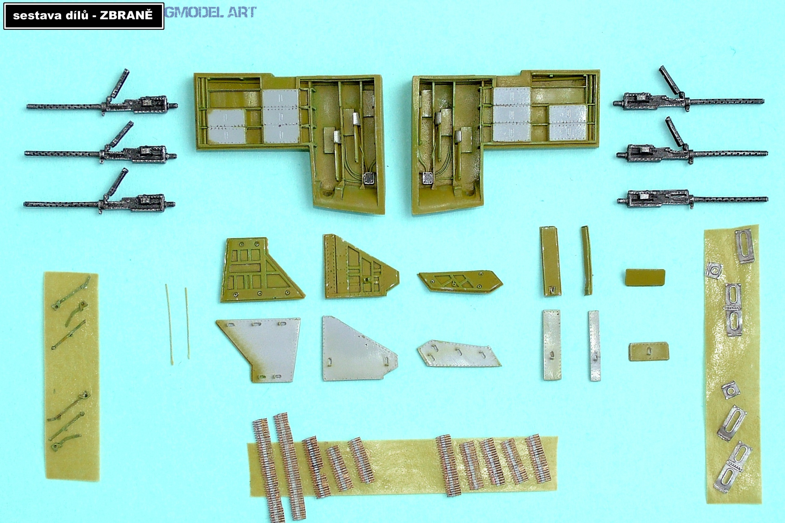
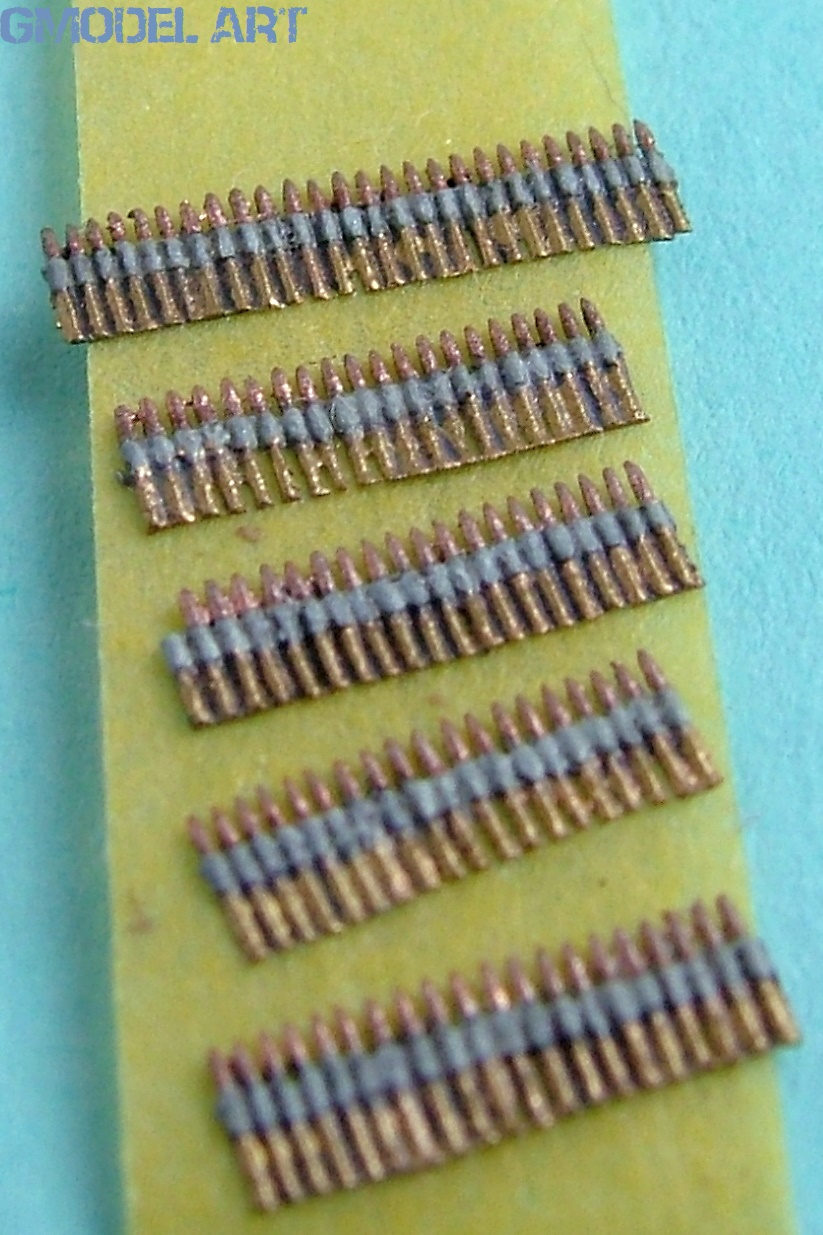
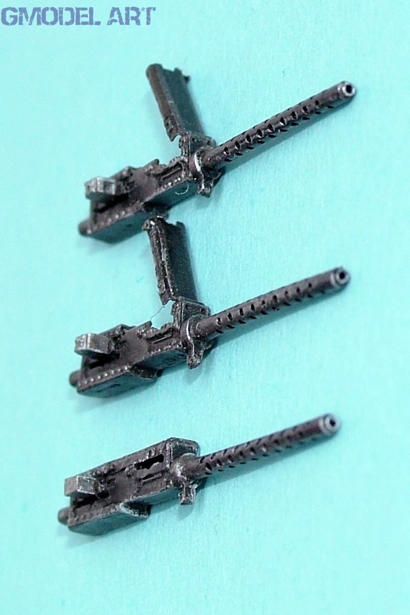
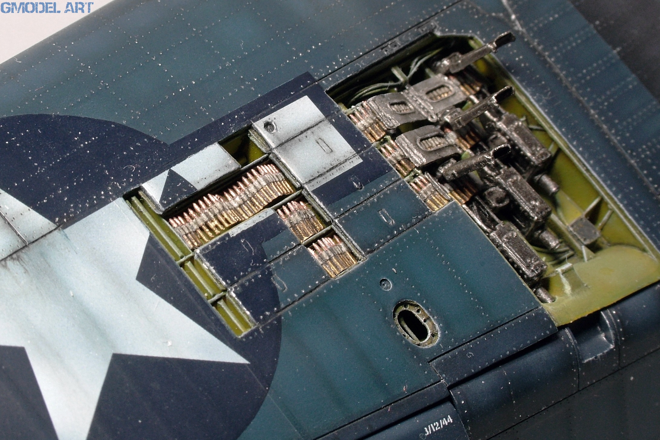
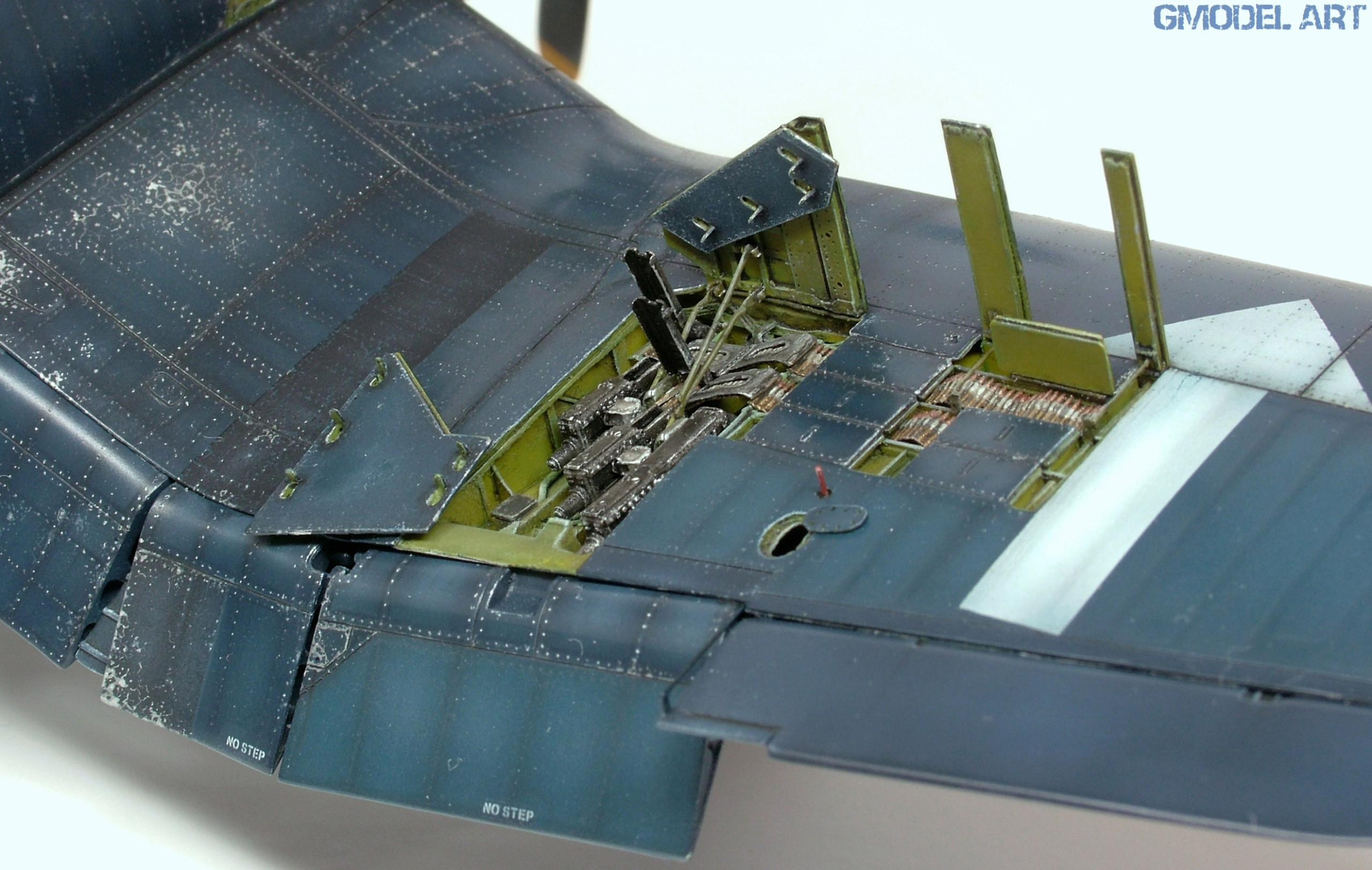
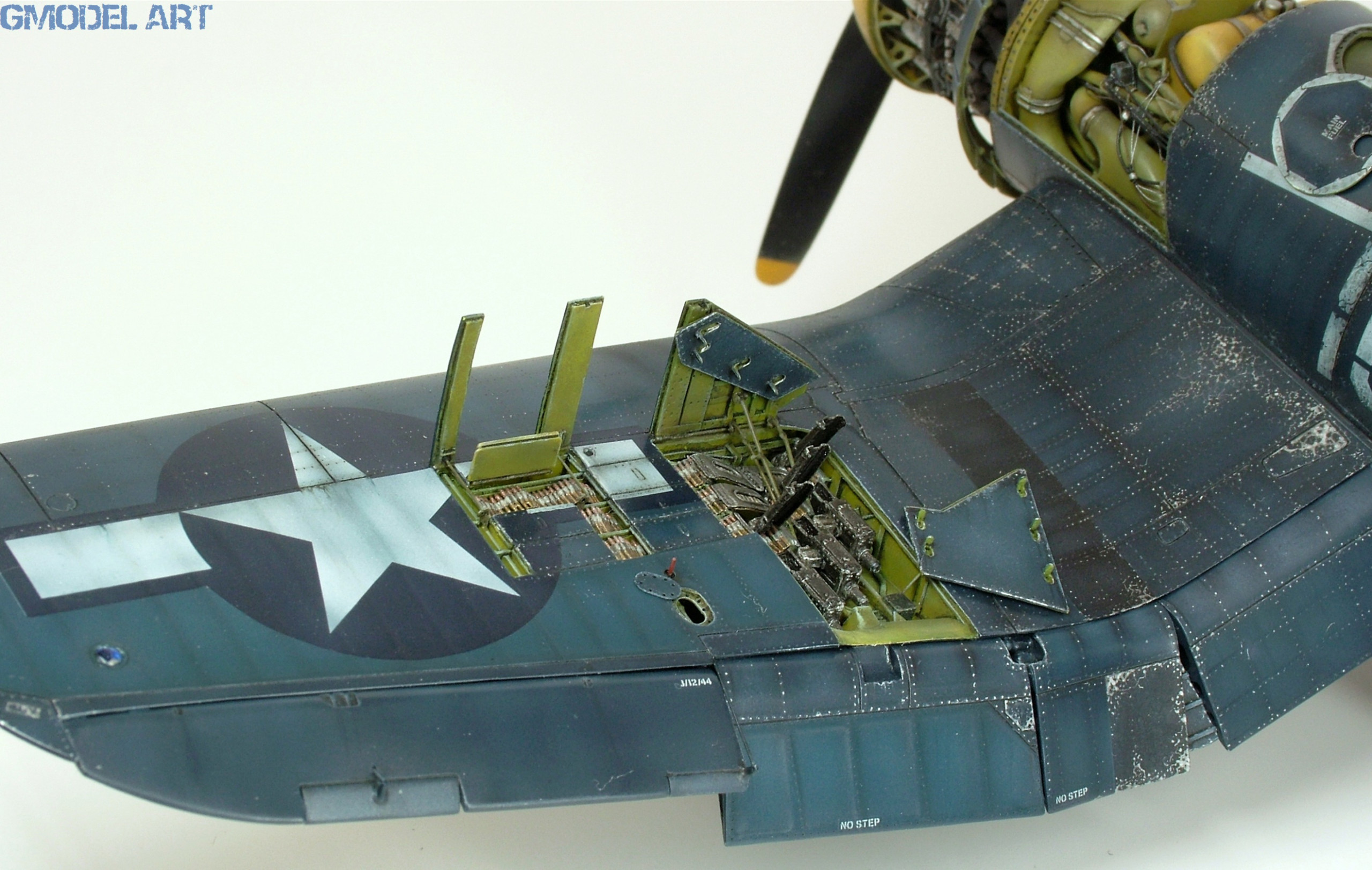
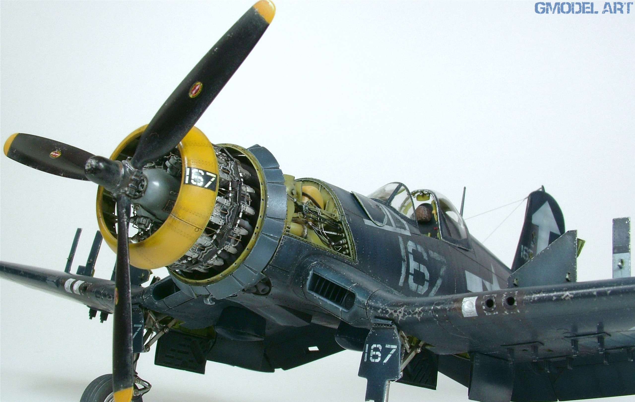
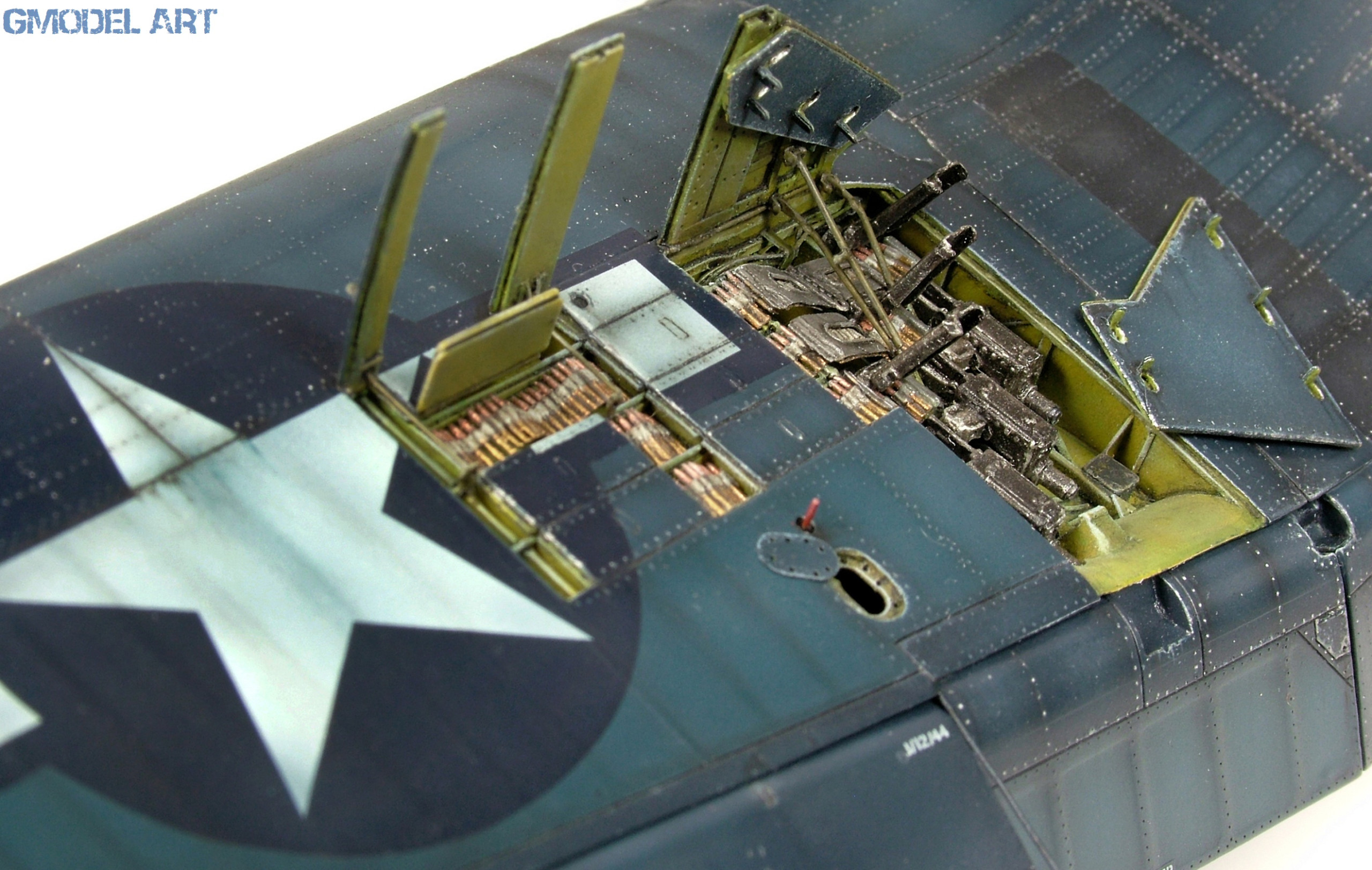
4. Weapons:
This portion of modeling was a “walk in the park”. Six 12.7mm large-caliber Browning machine-guns were completed with only a few parts from the Aires set and pasted metal locks were added to all new weapon pits. We can also substitute the not-so-model-like cover closing mechanism photo etchings with a new more precise circular cross-section made out of wire rather than that of the Aires etching and then add a couple electric cables in the pits.
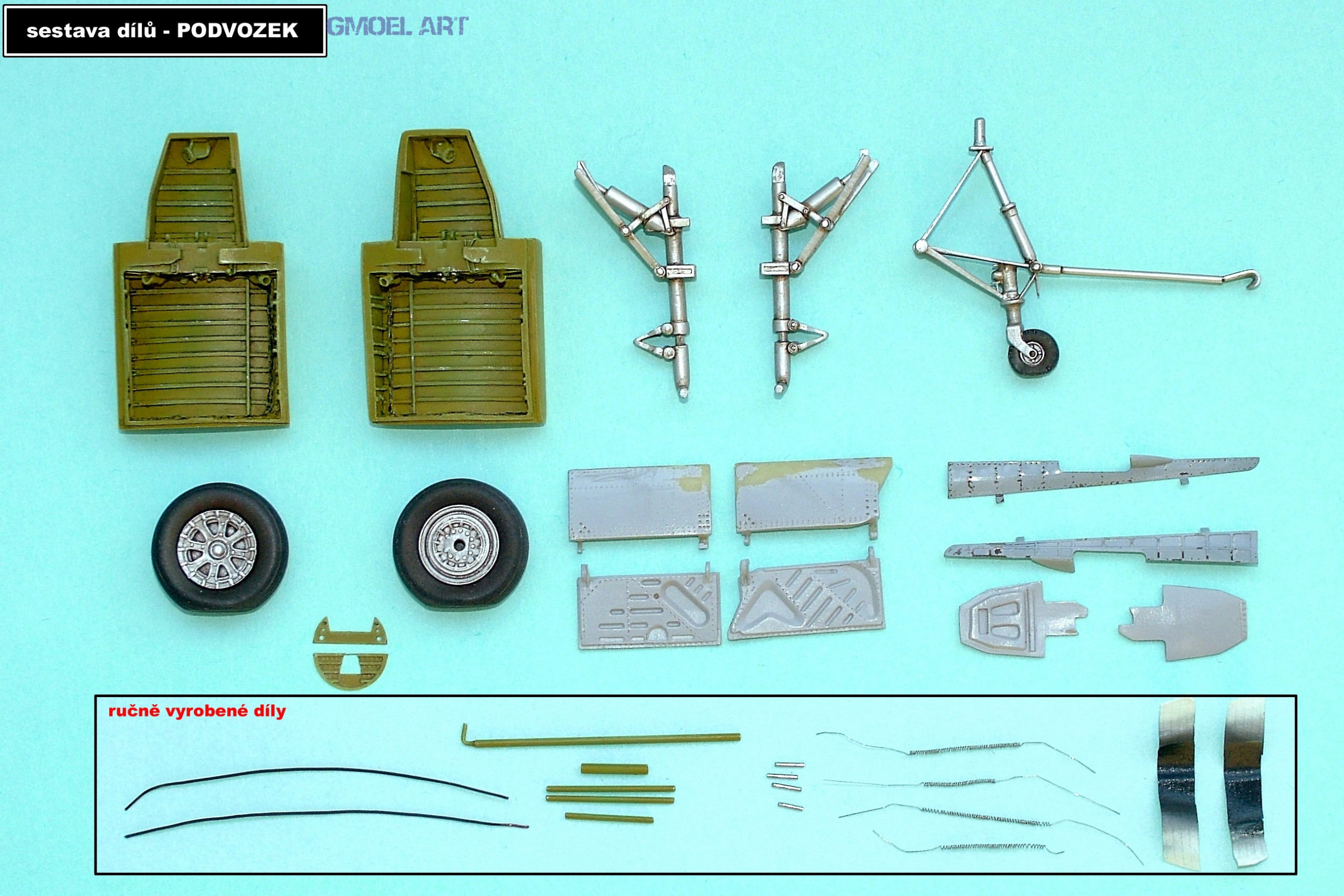
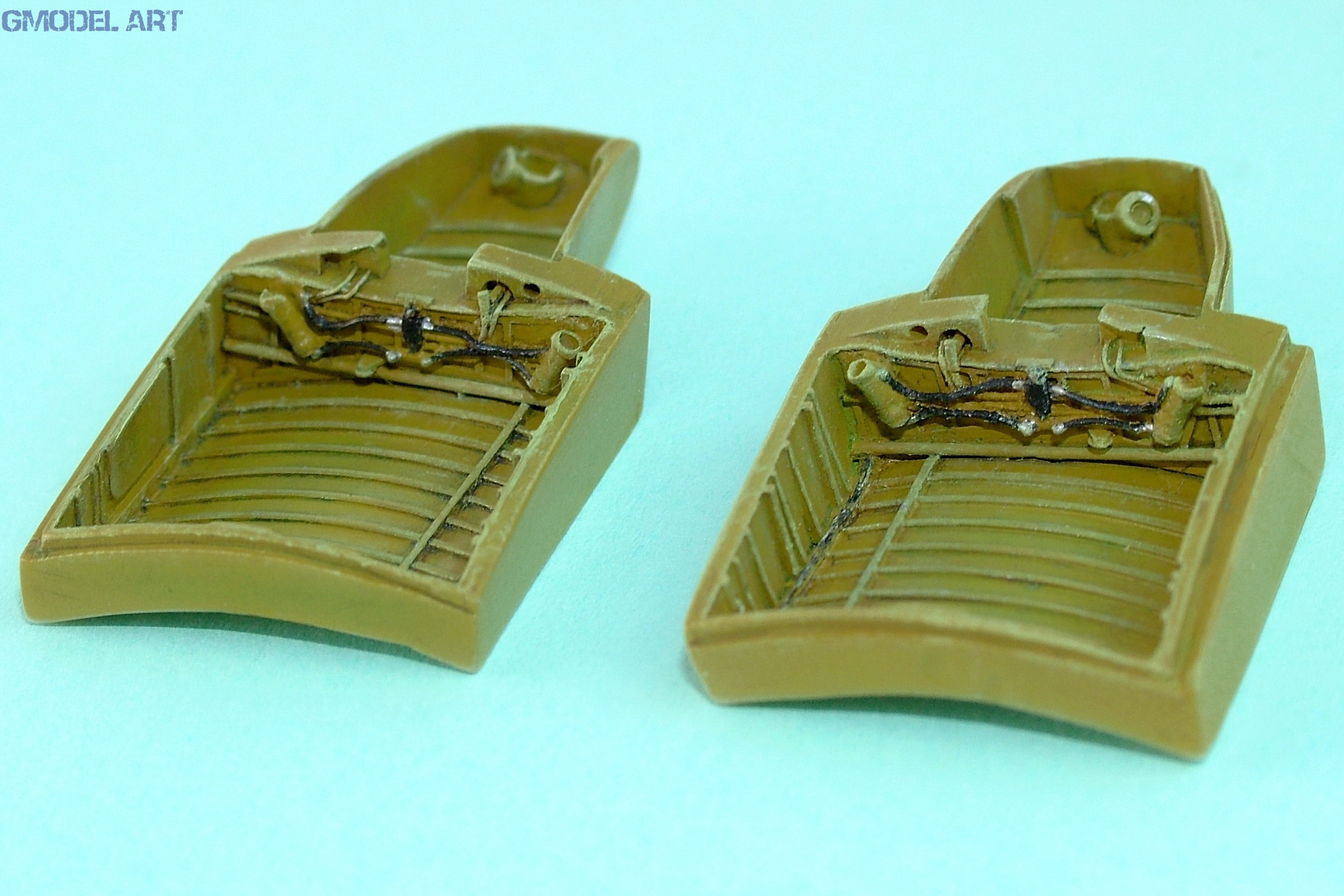
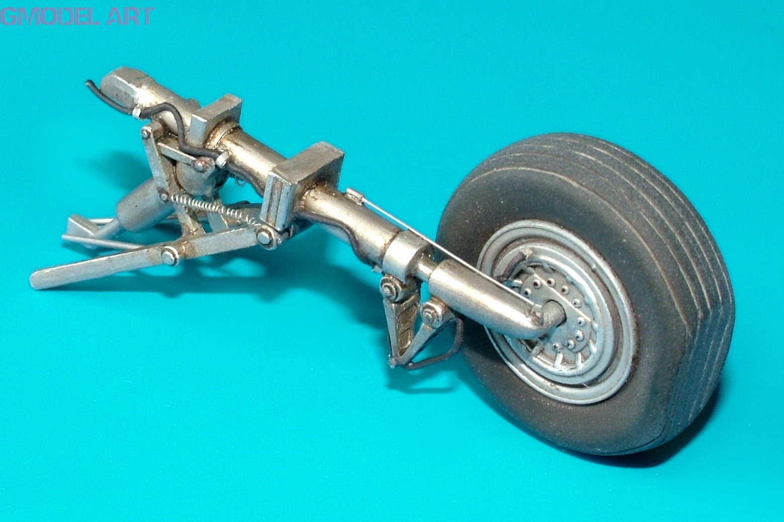
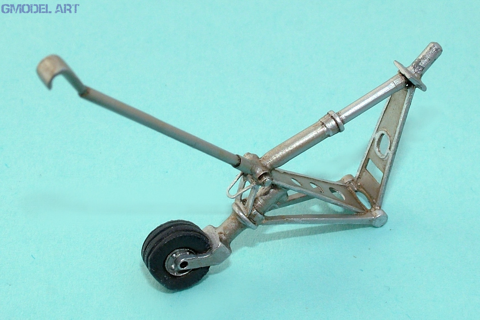
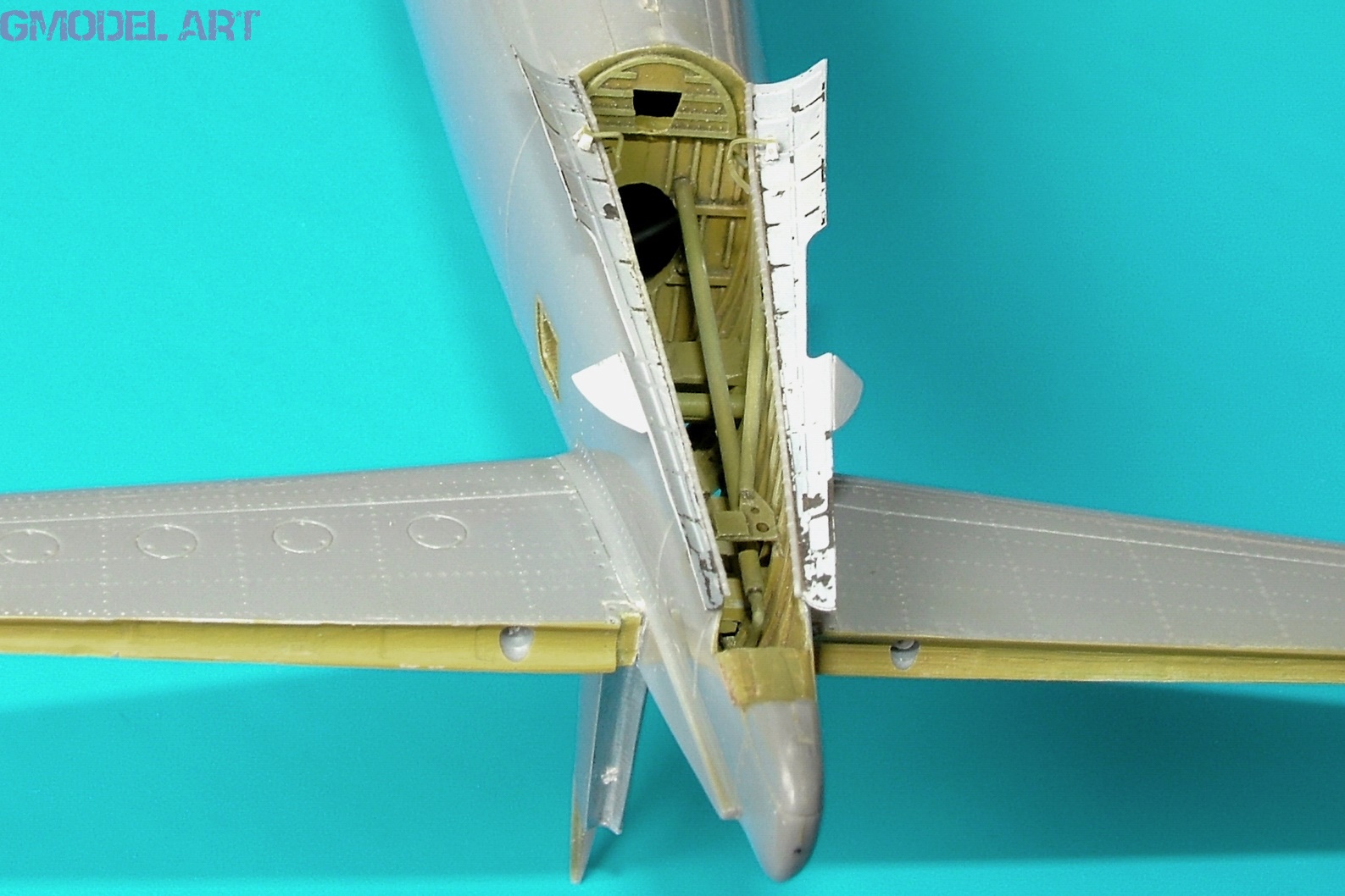
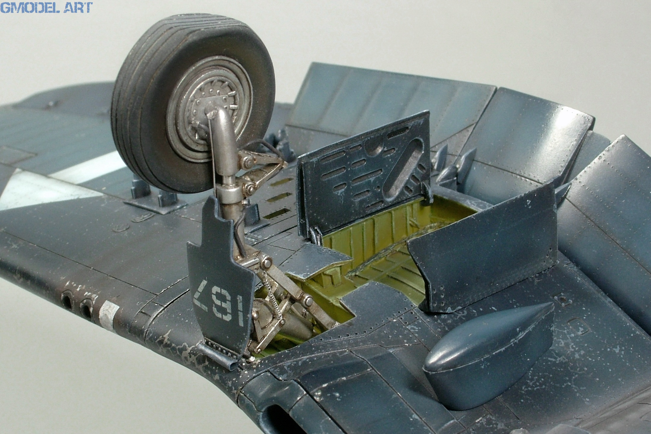
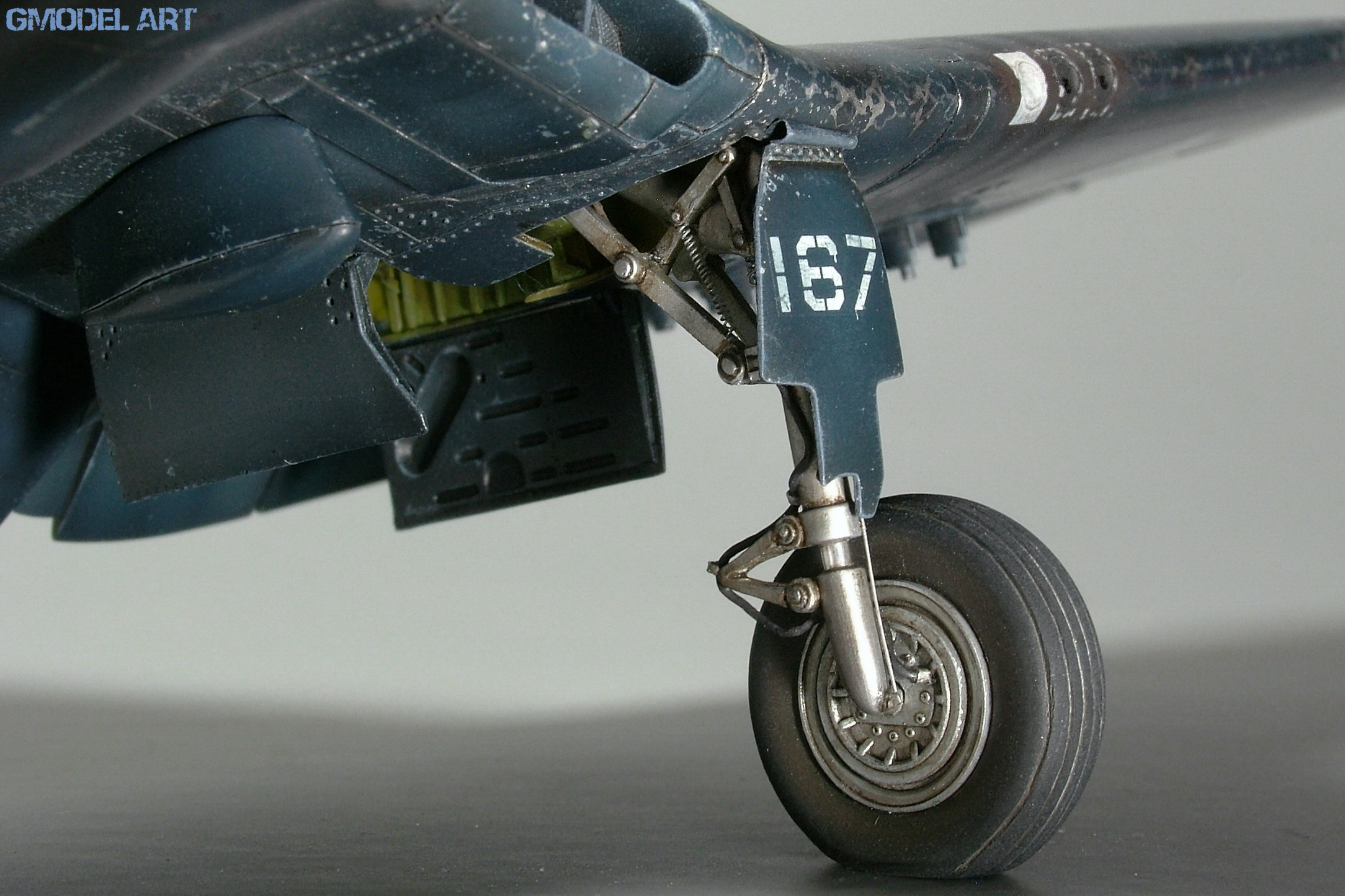
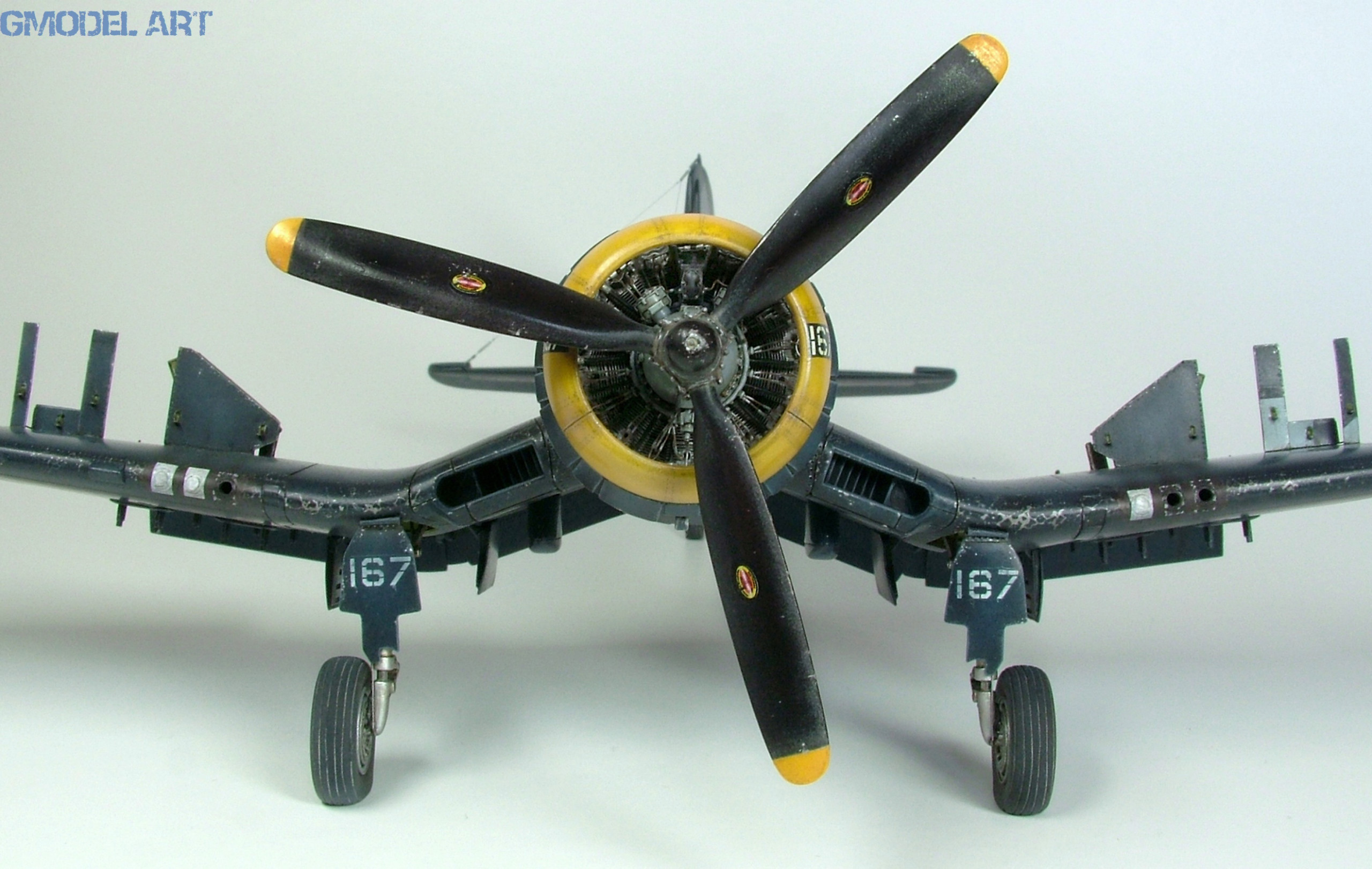
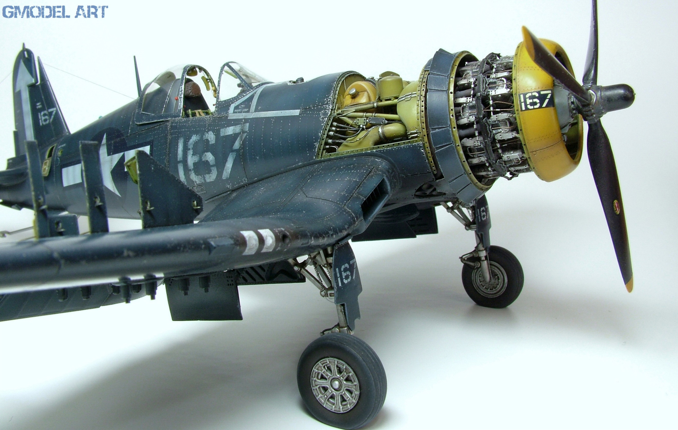
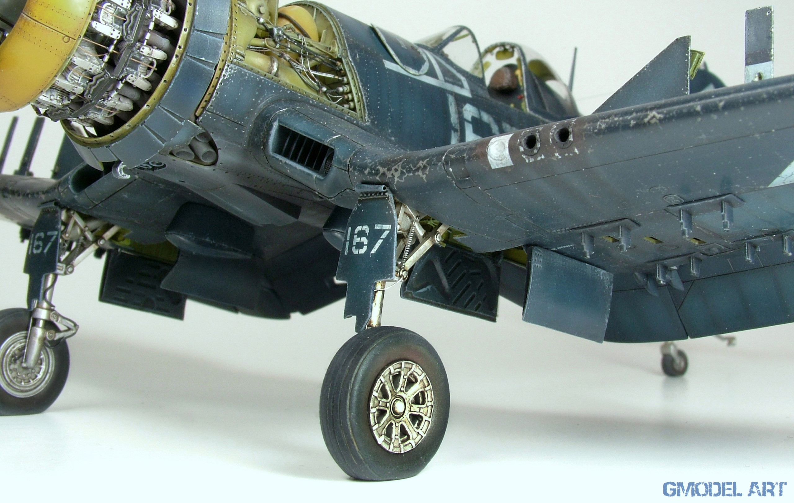
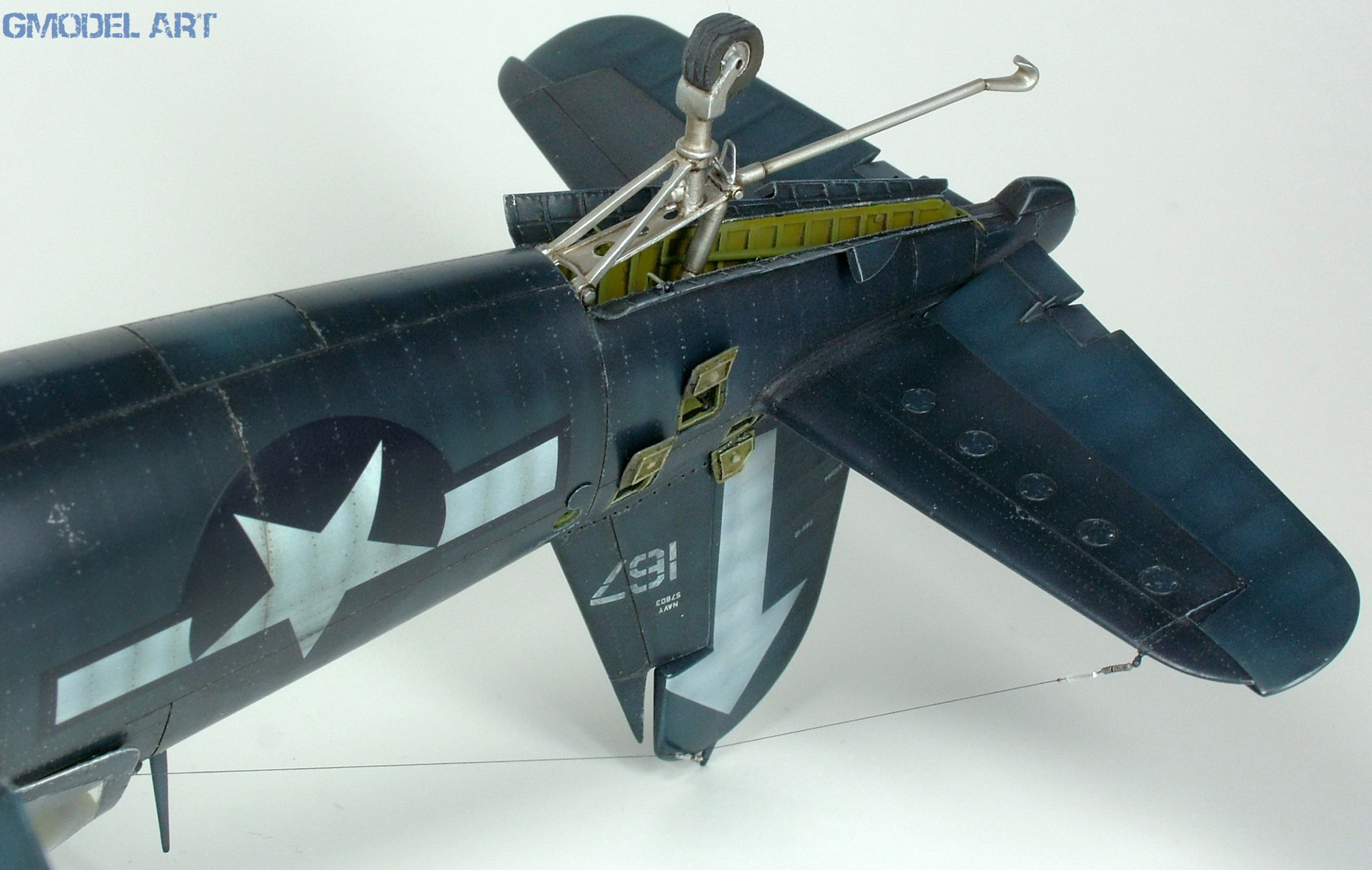
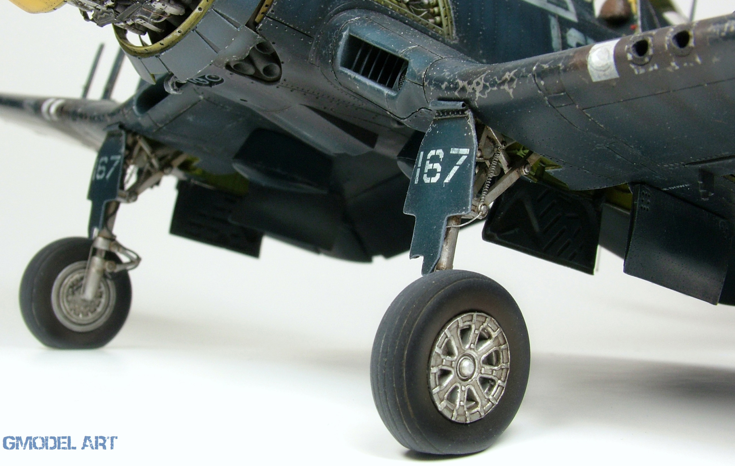
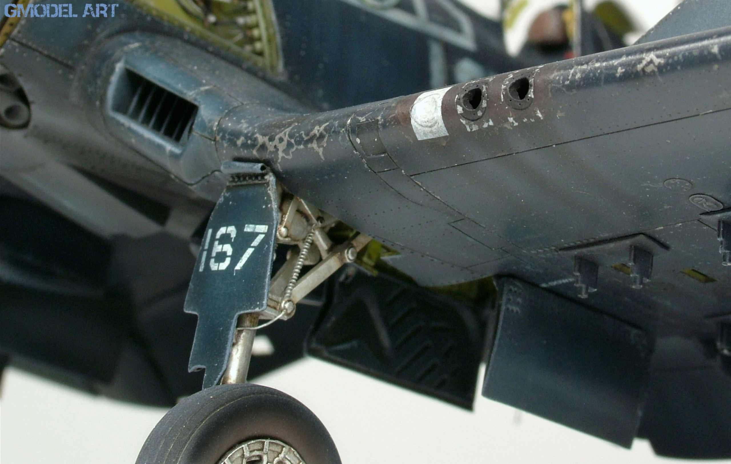
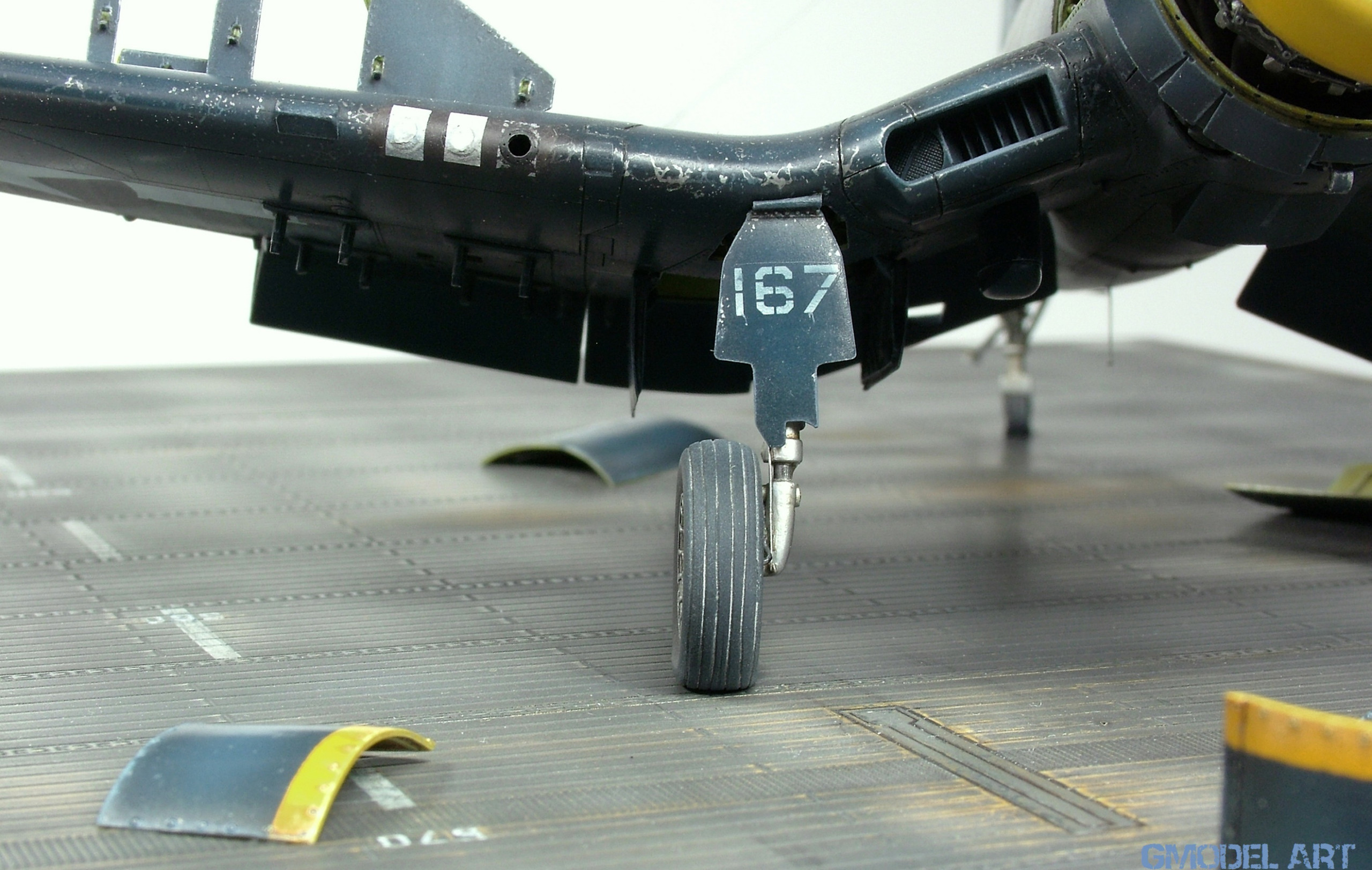
5. Under Carriage:
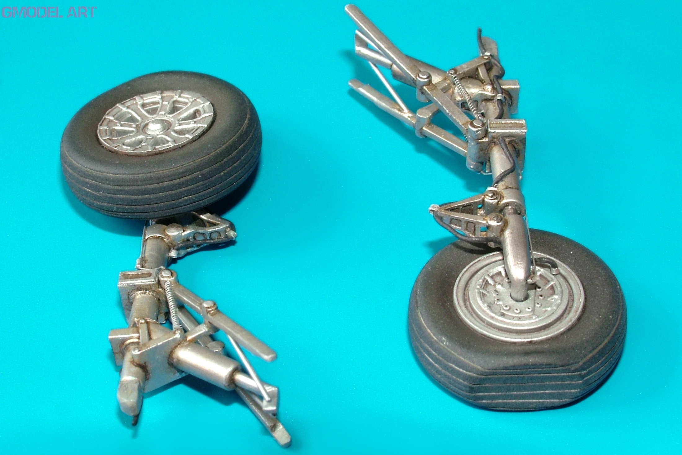
The undercarriage was considerably altered. First off, it is important to putty over any ugly markings on the main gears, cut off the original plastic shocks and replace them with new metal ones from injection needles. Add Aires etches and other different hand-made parts, for example the spring system, add spring and hydraulic segments, at the end brake lines made from lead wires.
I had problems with treading the tires and weighing them down with the mass of the aircraft.
I first traced treads on the tires with a pencil and then carefully cut tread by tread with a scalpel. I then got into, so to say “weighing”. Some modellers use the “hot screwdriver” method where they heat up the head of the screwdriver and then place it on the tire as to flatten or “weigh” it, I however proceeded the opposite direction a somewhat risky but credible method at that very carefully !!! Heat up the tires themselves over a flame so that the material softens at the right places but not melting or deforming the disk, then immediately press it on a glass table. This time luck was on my side and everything turned out well. Thanks to the softened plastic all tires were properly plump and rounded on the sides.
The making of the pistons out of injection needles that control the covers of the main gears and other rods in the aft shafts proved to be an easy job