article
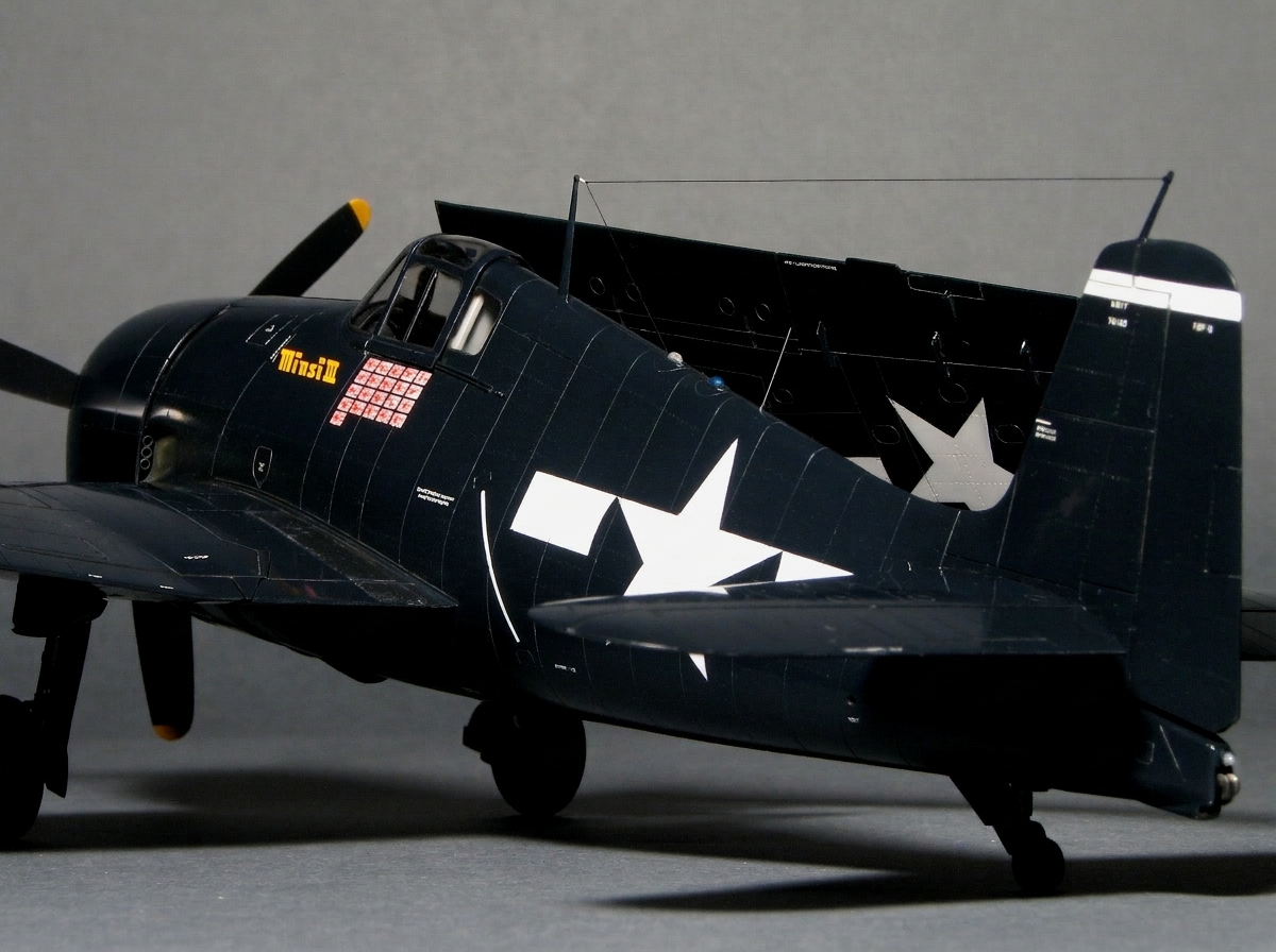
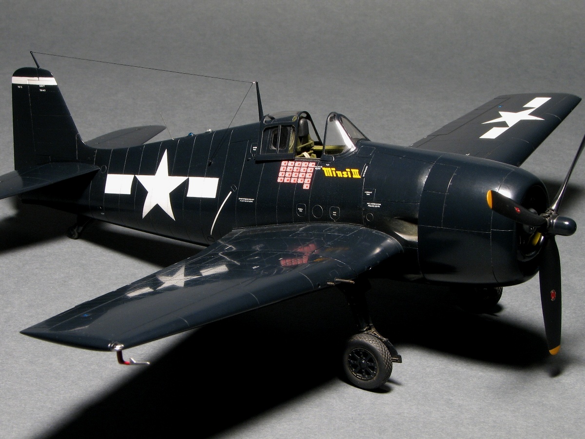
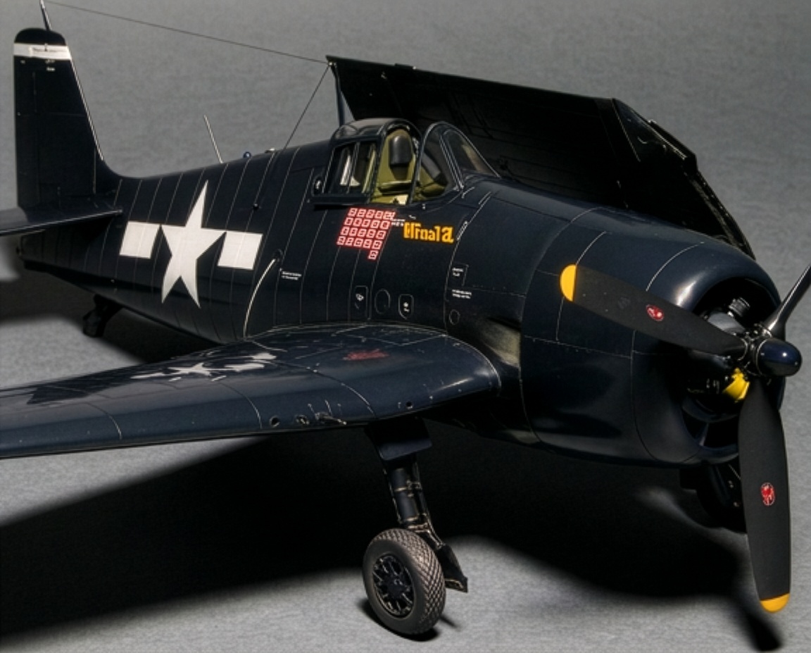
F6F-5 Hellcat “Minsi III” – Accurate 1/48 Scale Model Build with Folding Wings
Many modelers consider the Grumman F6F-5 Hellcat a solid and dependable wartime aircraft, but perhaps not one of the most spectacular subjects to reproduce as a scale model. I have often felt that the same description applies to many F6F-5 Hellcat kits.
The Hasegawa 1/48 scale F6F-5 Hellcat is, in my opinion, one of the better starting points available, but it is also somewhat uninspiring as a finished model. The Eduard kit offers sharp detail and excellent surface work, yet its overall shape does not completely capture the massive, rugged and powerful appearance of the real Grumman F6F-5 Hellcat.
This project therefore had two main objectives.
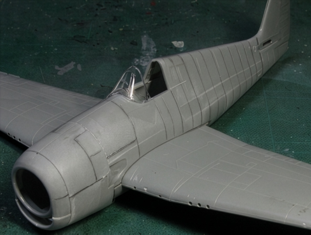
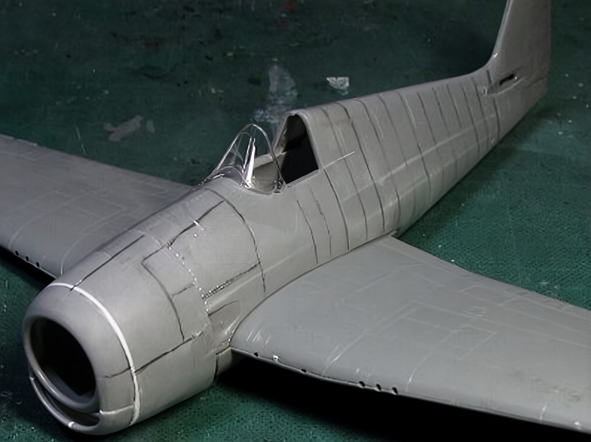
The first was to reproduce the characteristic contours of the real F6F-5 Hellcat as accurately as possible, particularly its wide fuselage, bulky cowling and unmistakable “cat smile.” The aim was not simply to add more detail, but to correct the fundamental shape of the model so that it would convey the tough and aggressive presence of the real aircraft.
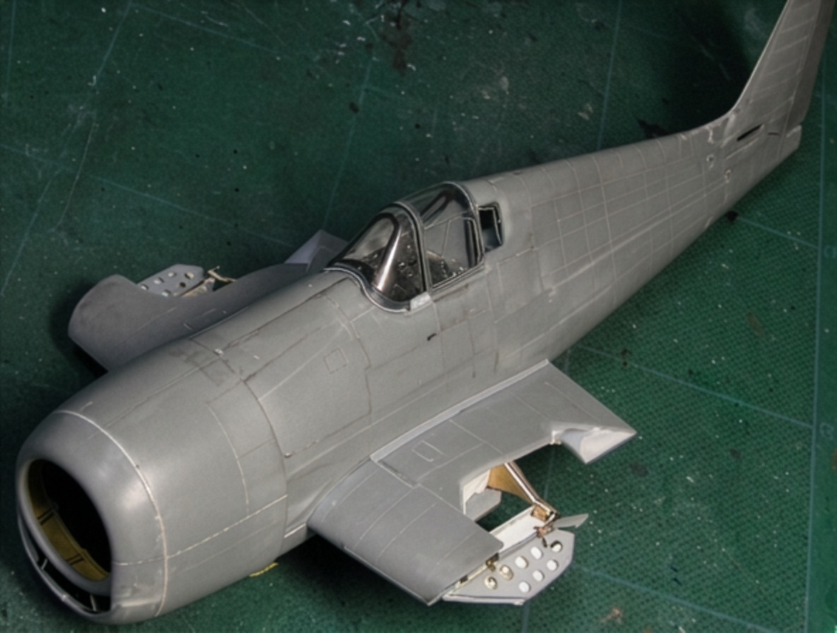
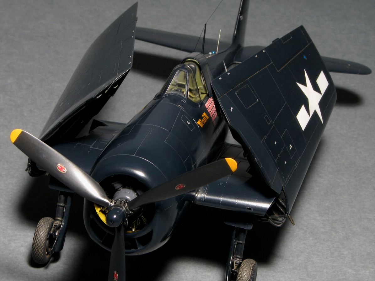
The second objective was to build a fully functional folding-wing mechanism. A Hellcat with its wings folded is an impressive subject at a model show, so I wanted the completed 1/48 scale model to reproduce that feature while still maintaining reasonable scale accuracy, structural rigidity and smooth movement.
These two objectives created a demanding modeling project: correcting the shape of the aircraft while simultaneously engineering a folding-wing system strong enough to work repeatedly.
Kit Review
No 1/48 scale kit has, in my opinion, completely captured the true shape of the F6F-5 Hellcat.
Among the available kits, I consider the Hasegawa 1/48 scale kit the best starting point, although it is far from perfect.
The fuselage is approximately 3 mm (0.12 in) too short. The cowling is too round, while the windshield and canopy are too low and wide. The thickness of the center wing section is reasonably close to the real aircraft, but the kit wing tapers instead of maintaining the consistent thickness found on the actual aircraft.
The Eduard F6F-5 Hellcat is a newer kit and has some excellent features. The windshield and canopy are particularly well shaped. However, the cowling is too square and the cross-sectional shape does not reproduce the broad, flat character of the real aircraft. The main wing is also approximately 1 mm (0.04 in) too low, while the center wing thickness suffers from the same tapered treatment found in the Hasegawa kit.
The Otaki 1/48 scale kit has a general appearance similar to the Hasegawa kit. Some modelers consider its characteristic “cat grin” better than Hasegawa’s, but overall I believe the Hasegawa kit provides the superior basic shape.
The Hobby Boss 1/48 and Trumpeter 1/32 F6F Hellcat kits are not considered further in this project.
The most important problem, however, is shared by virtually all of these kits: the cowling and fuselage are too narrow.
The real aircraft is noticeably wider than the scale models suggest. I believe this error originated with inaccurate drawings, possibly resulting from a misunderstanding of the original fuselage-width data. Correcting that fundamental problem became one of the most important parts of this project.
Correcting the Fuselage
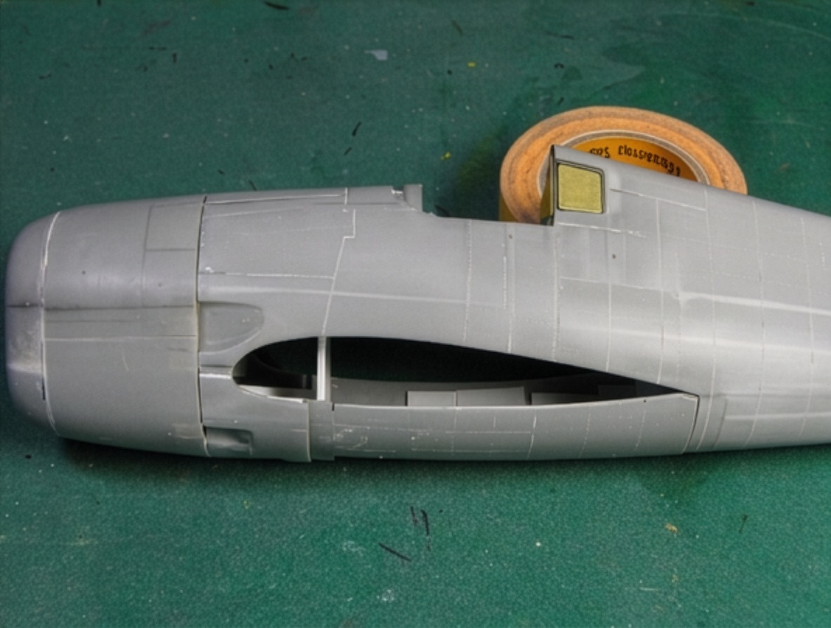
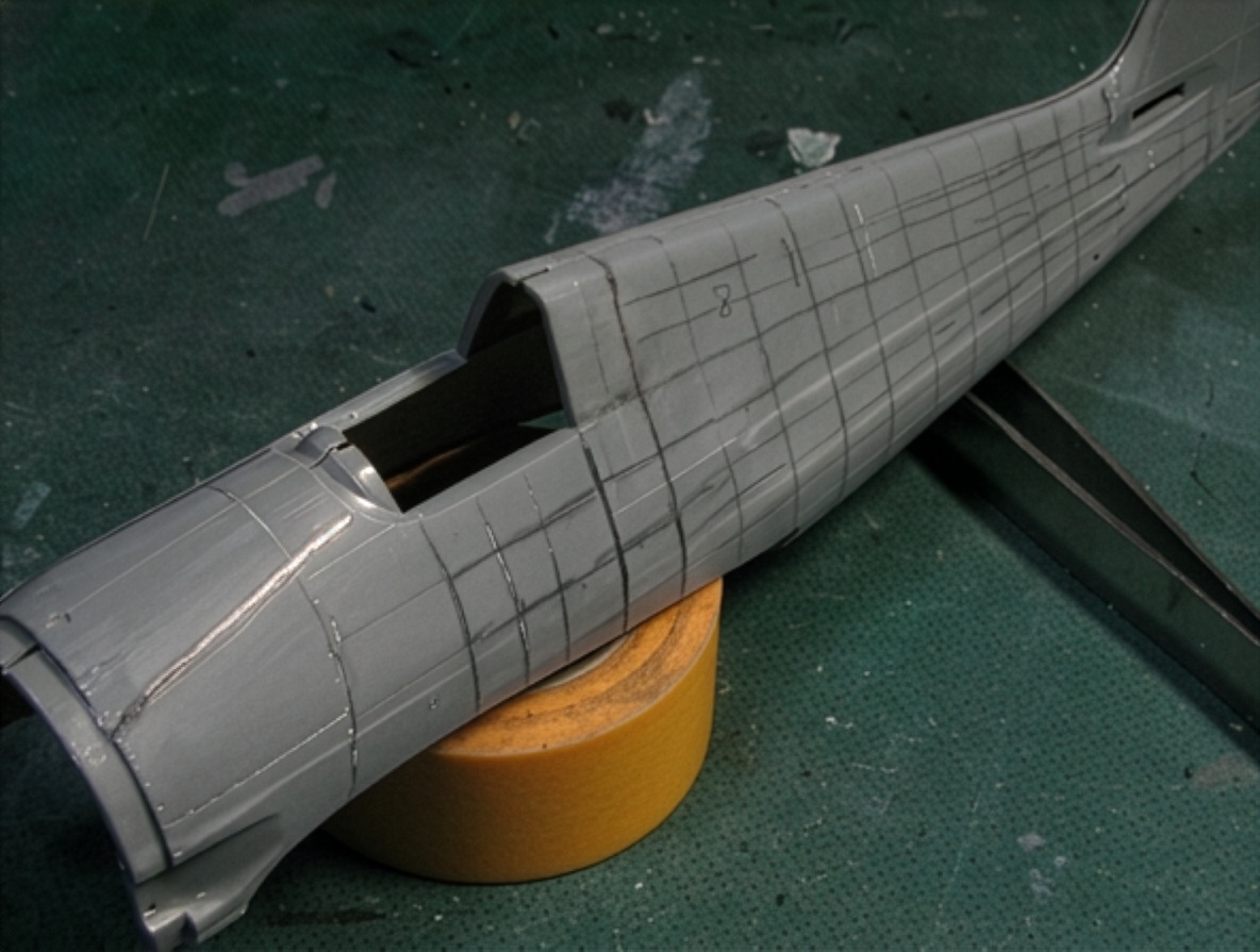
The Hasegawa fuselage was extended by 3 mm (0.12 in).
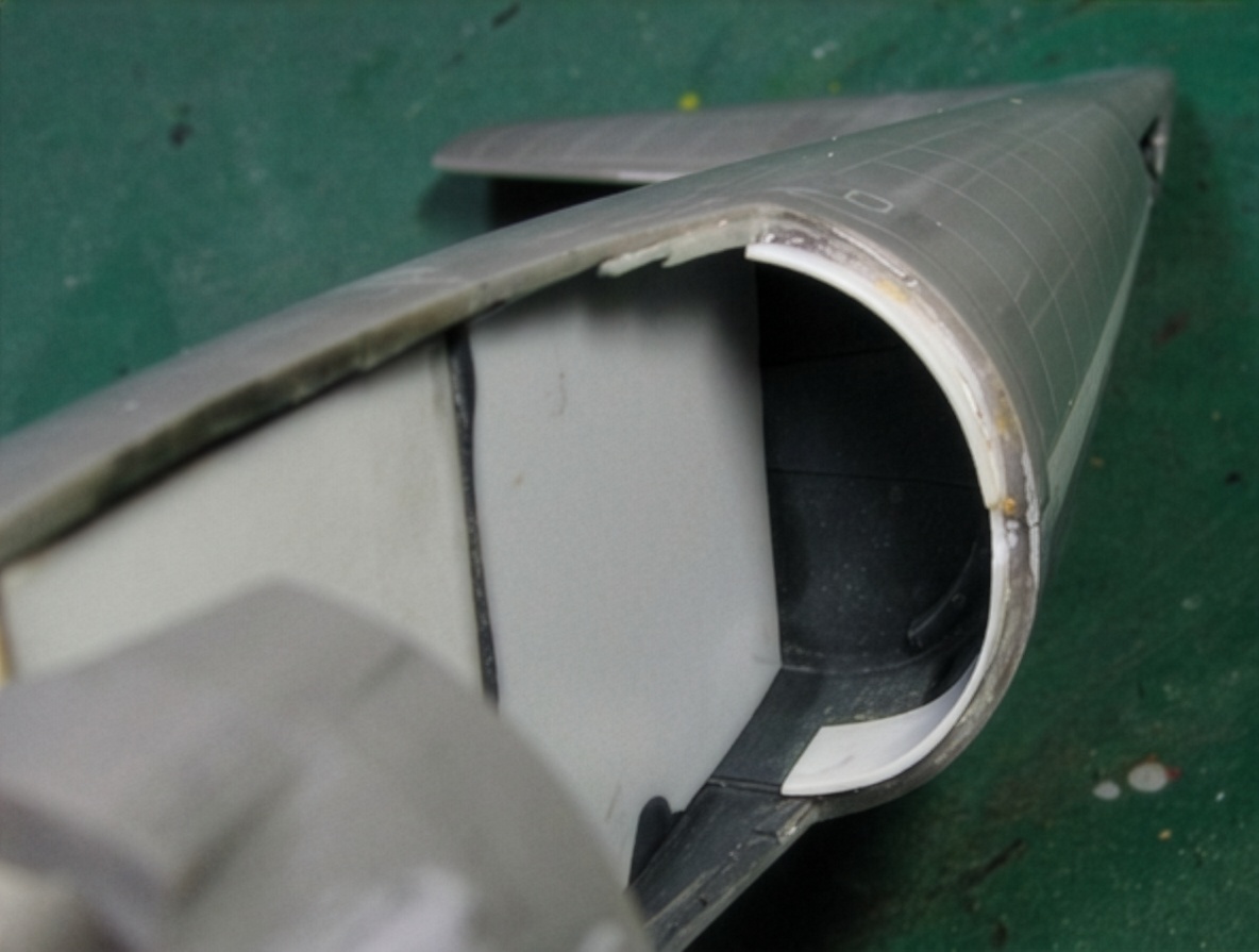
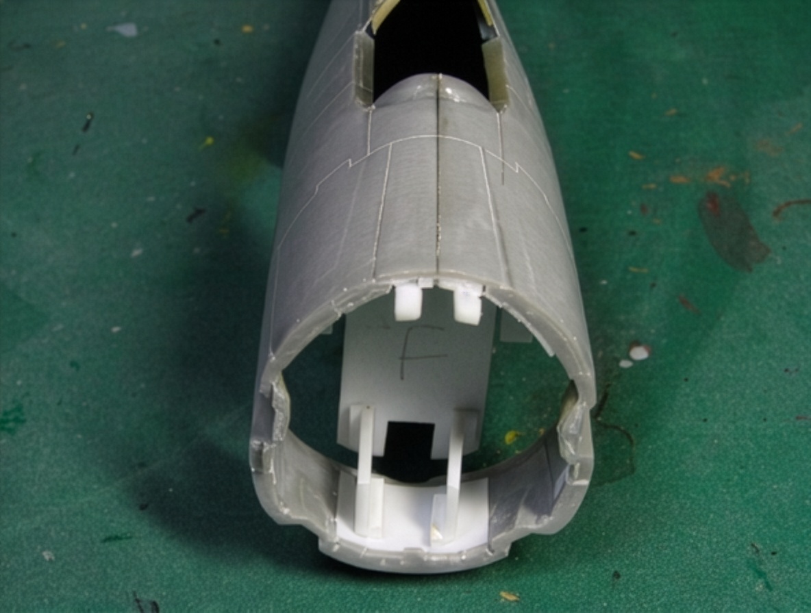
The two fuselage parts were cut at different locations and then joined with CA glue. After the parts were connected, the fuselage section was cut again and carefully bent to reproduce the correct cross-sectional shape.
The flat area of the real F6F-5 Hellcat fuselage is considerably wider than represented by the kit. To correct this, I made shallow cuts on the inside of the plastic fuselage and carefully bent the parts outward until the correct profile was achieved.
I use CA glue for most of the main structural joints. I do not particularly like conventional plastic cement for these modifications because the joint can later sink as the solvent continues to affect the plastic.
Internal reinforcement with Plaban, or styrene sheet, is essential when making these kinds of structural corrections. Bent plastic has a tendency to return toward its original shape over time. The internal reinforcement prevents this and preserves the corrected fuselage geometry.
Once the structural work was completed, the entire fuselage surface was sanded with coarse abrasive paper and prepared for the subsequent finishing work.
Correcting the Hellcat Cowling
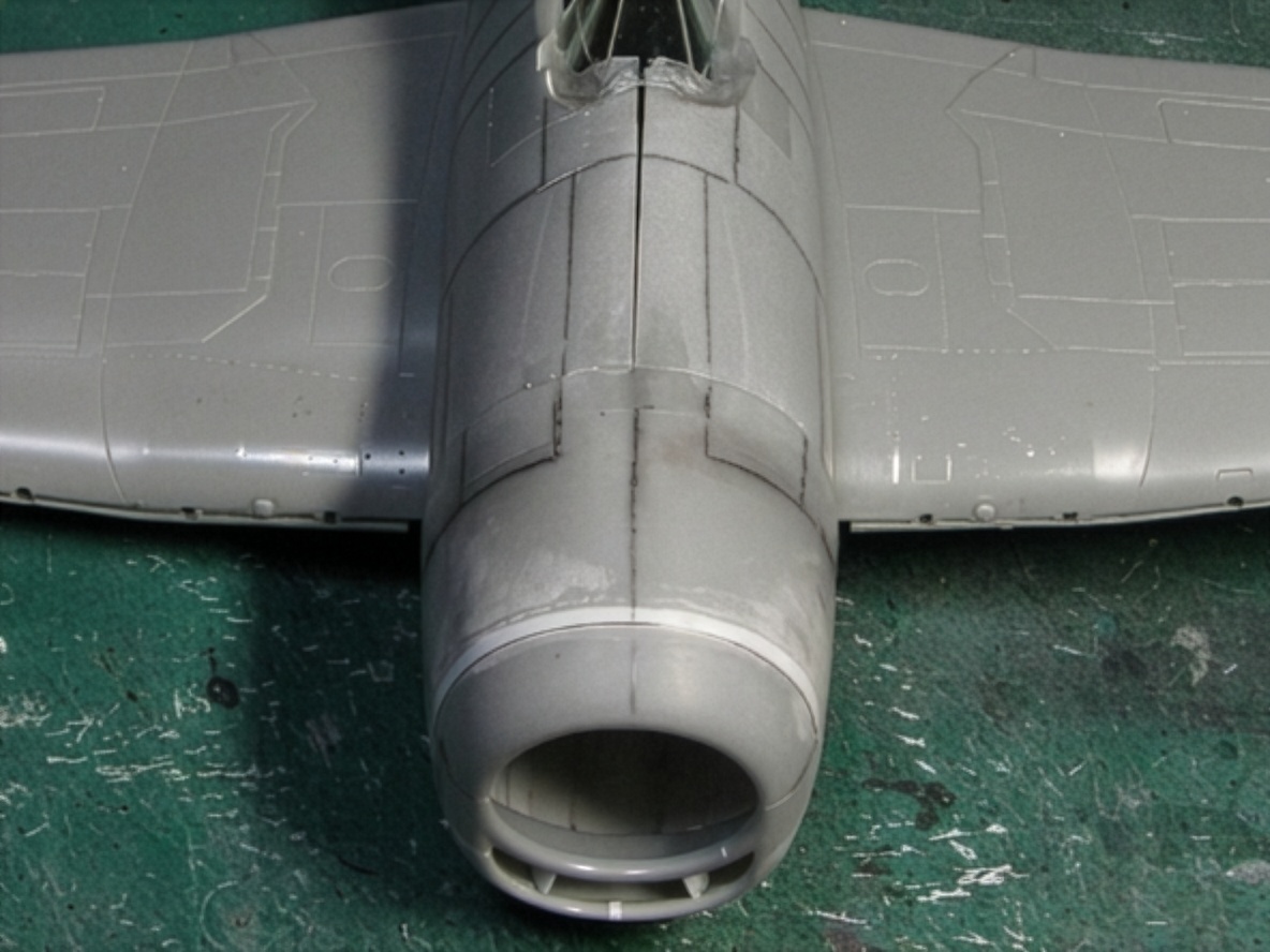
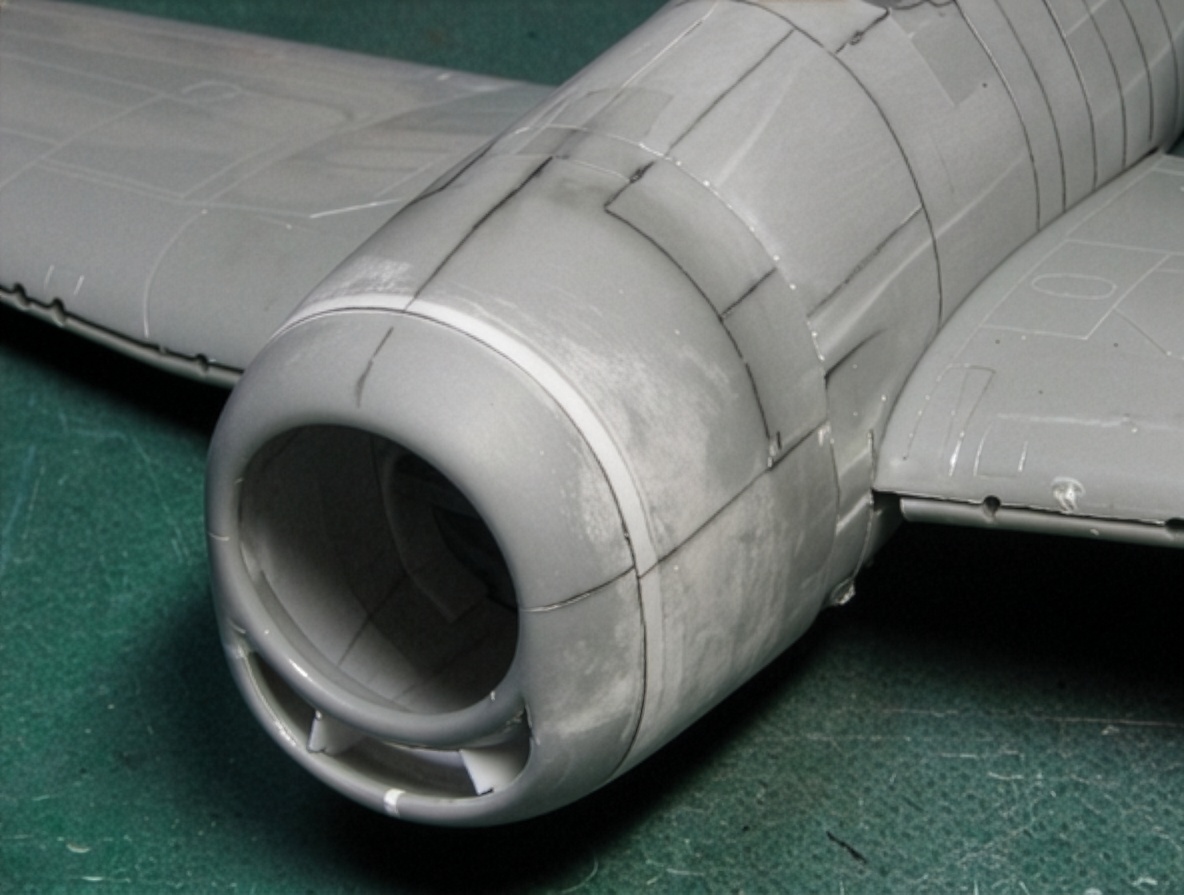
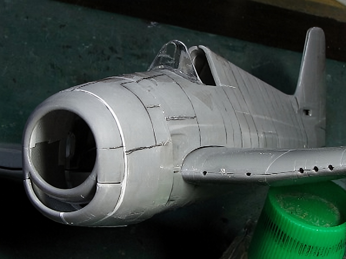
The characteristic “cat smile” of the F6F-5 Hellcat is one of its most recognizable features, yet it is incorrectly represented in many scale models.
The problem comes from misunderstanding the relationship between the different parts of the cowling opening.
On the real aircraft, the upper cover and upper intake lip have essentially the same rounded form. The lower lip, however, is different. It is slightly wider and lower and does not form a true circle.
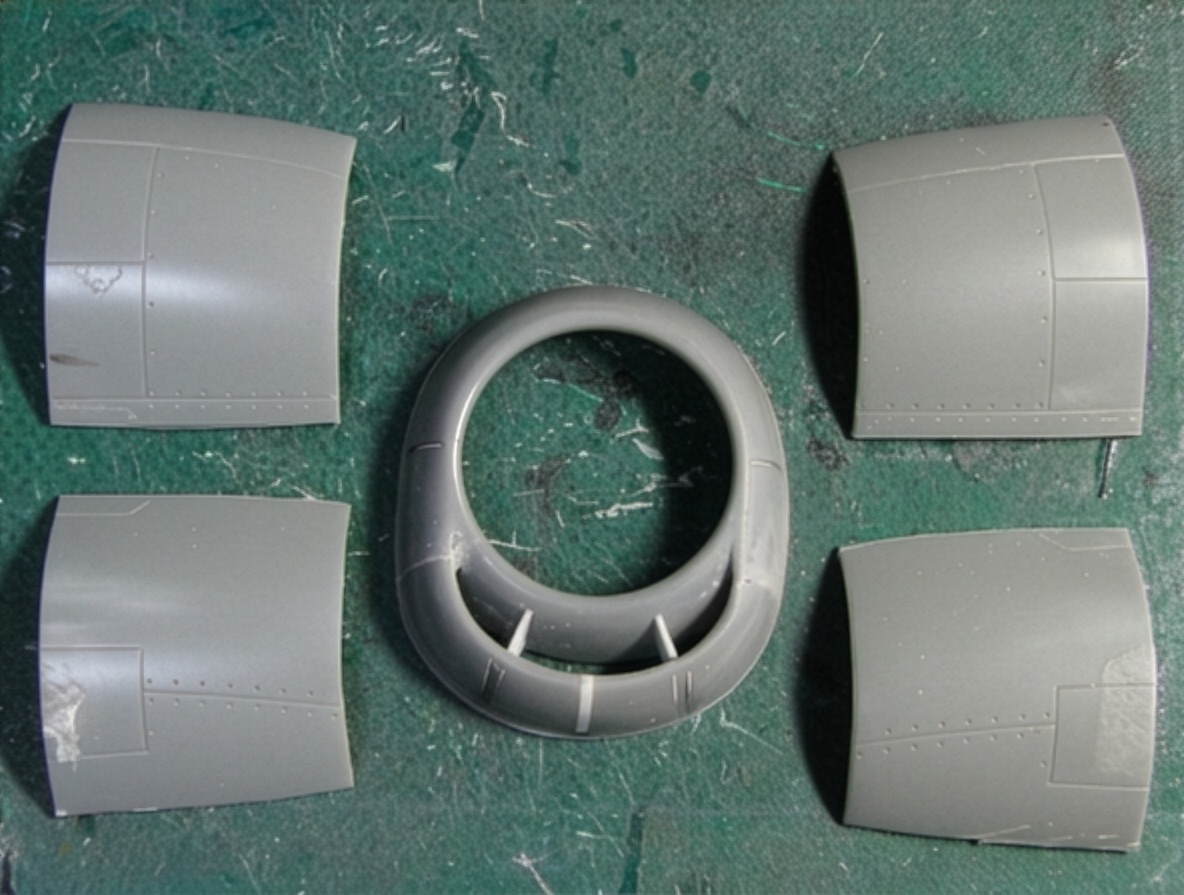
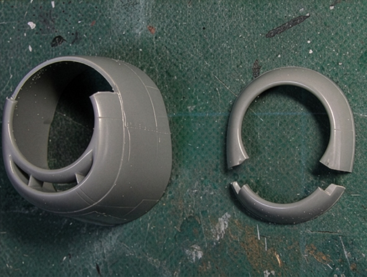
To reproduce this geometry, parts from additional kits were combined. The upper front cover was cut from the original kit cowling, while the upper oil-cooler and intercooler intake lips were taken from other kit components.
The upper front cover and upper intake lip were then assembled and the interior filled with putty.
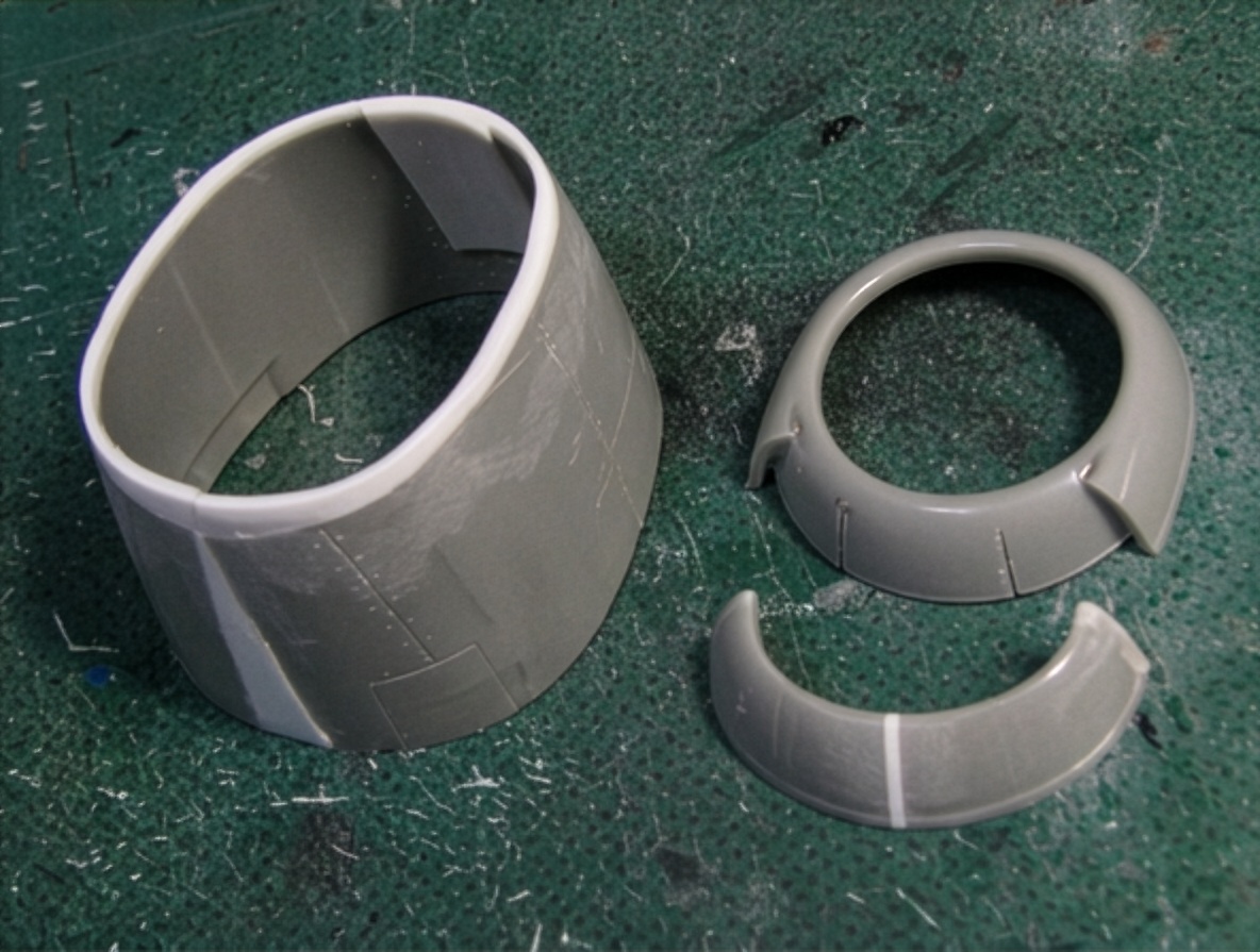
The lower intake lip was widened, while the rear cowling cover was enlarged using white styrene sheet.
The corrected cowling dimensions were approximately 33.5 mm (1.32 in) wide and 39 mm (1.54 in) high.
This correction makes a major visual difference because the broad cowling is one of the features that gives the F6F-5 Hellcat its characteristic massive appearance.
Lower Fuselage and Tail
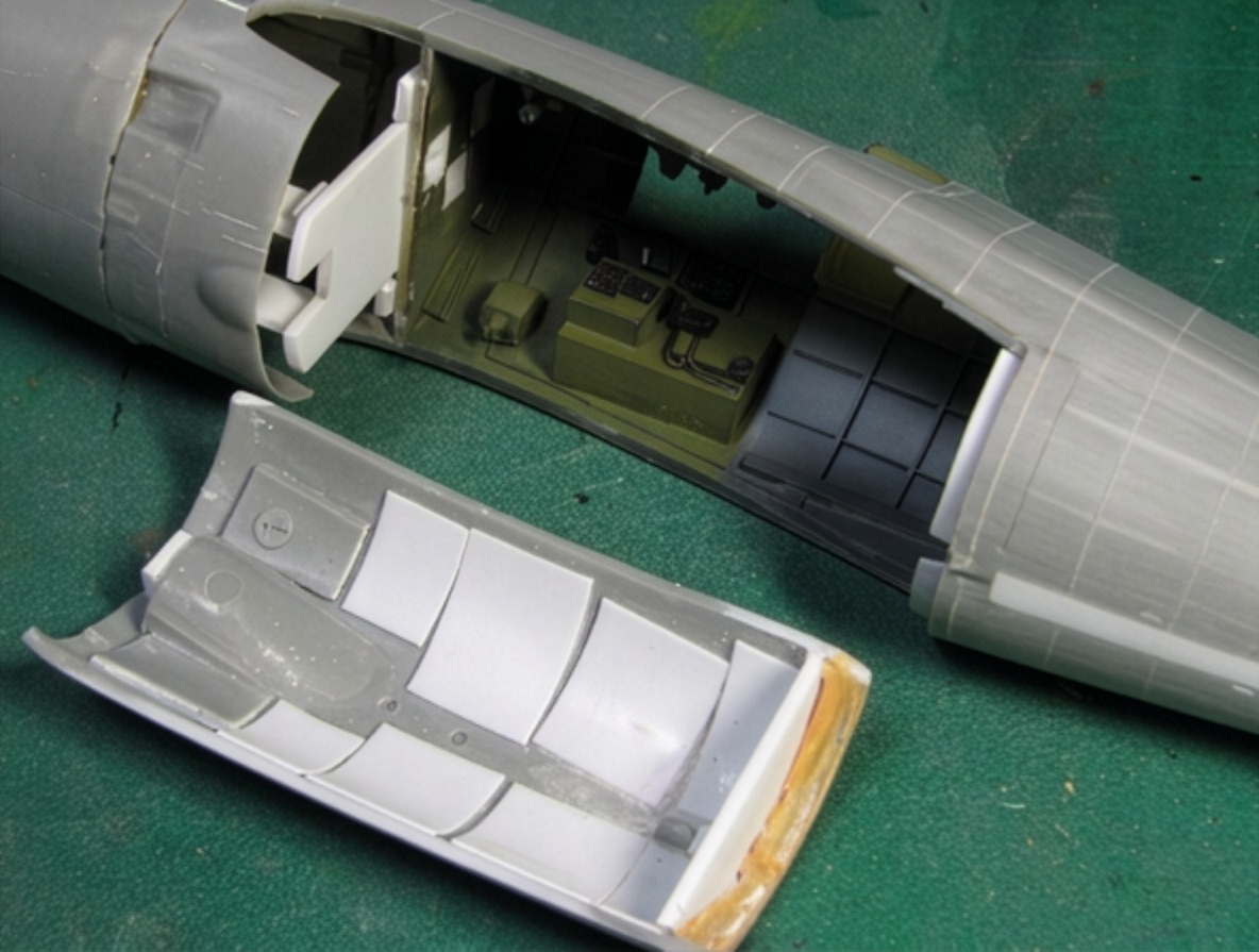
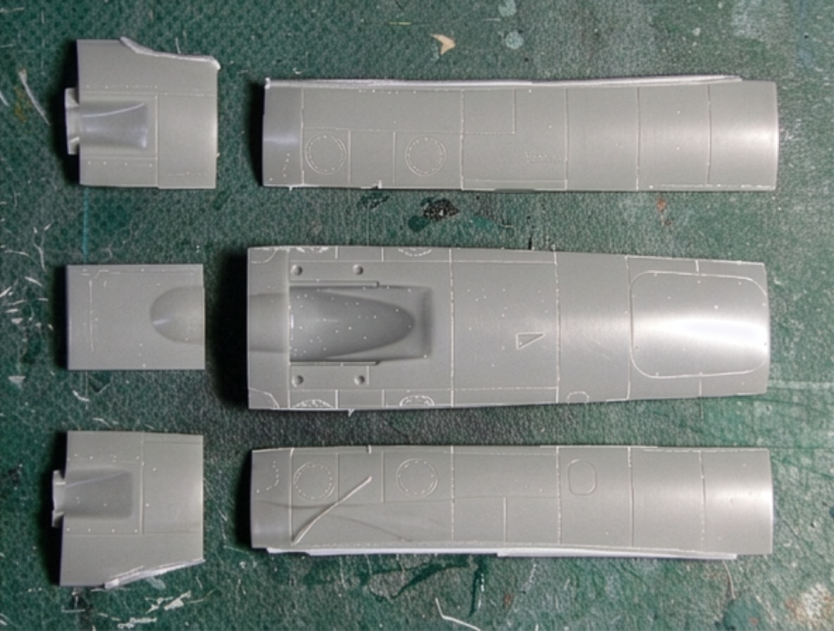
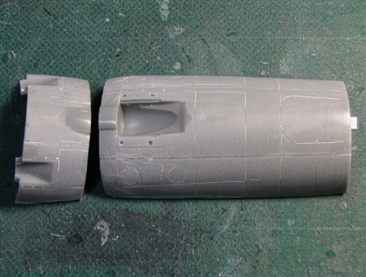
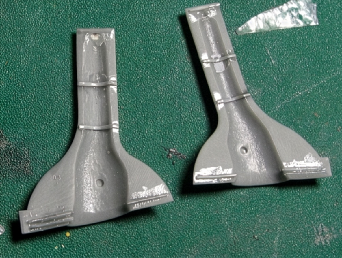
The central portion of the lower fuselage was widened using parts from two kits.
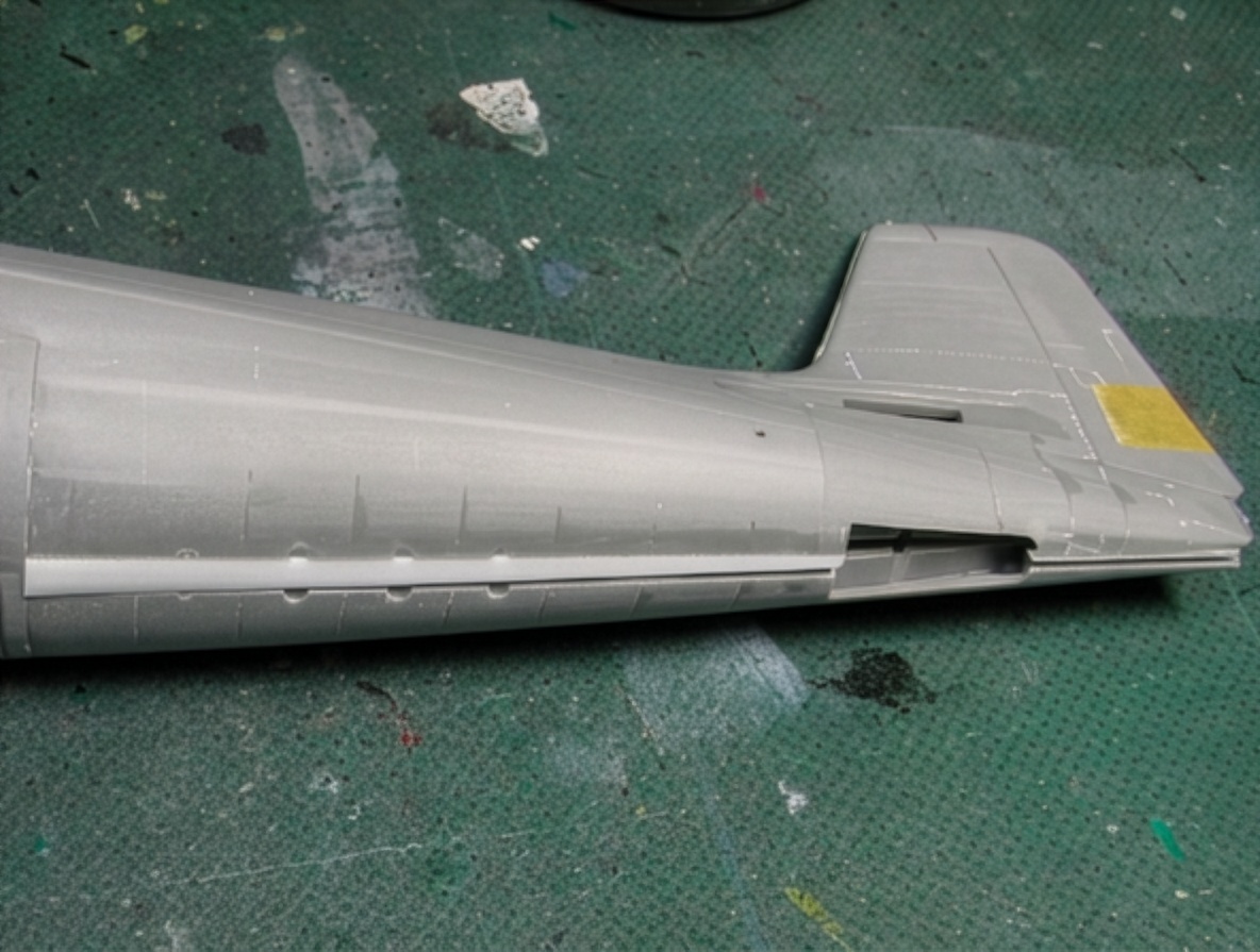
The two sections were joined and reinforced internally. The tail fin was extended by approximately 2 mm (0.08 in), while the length of the cowling was increased by another 1 mm.
These modifications significantly increased the overall cubic volume of the model and brought the fuselage closer to the bulky proportions of the real F6F-5 Hellcat.
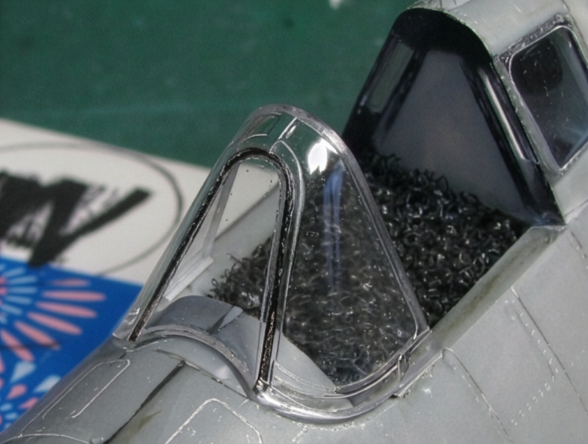
An Eduard windshield was used during the correction process. The comparison between the corrected fuselage and the original Eduard fuselage showed how square the original cross-section was.
The Folding Wing
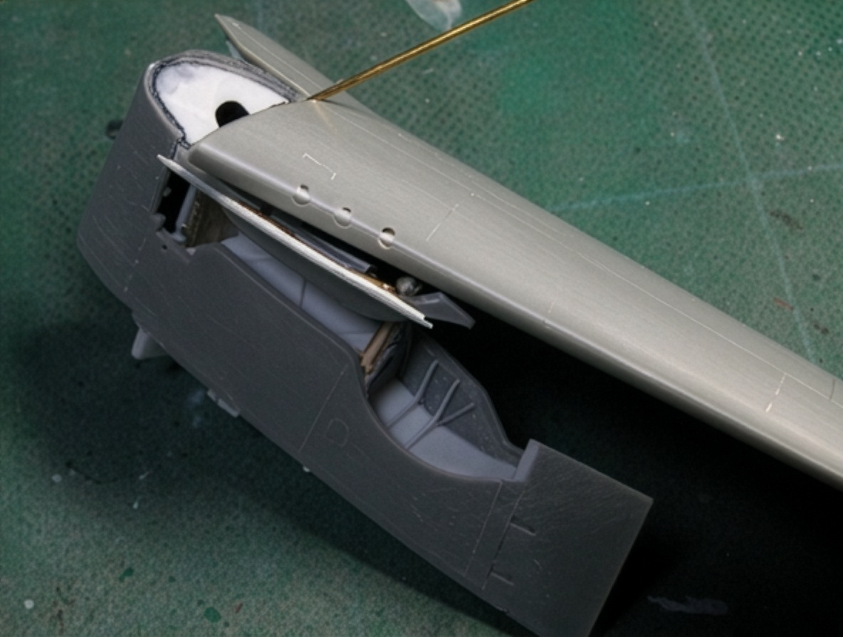
The second major challenge of this project was the folding wing.
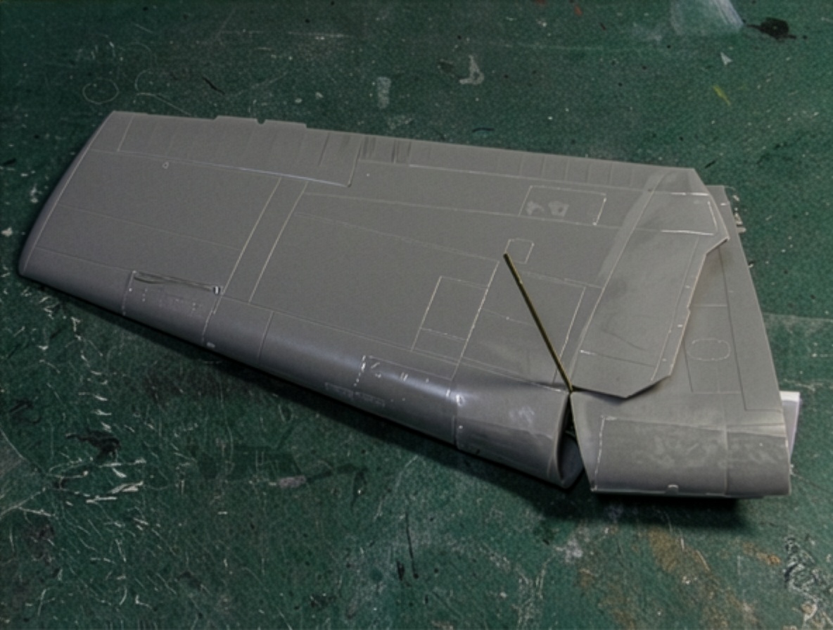
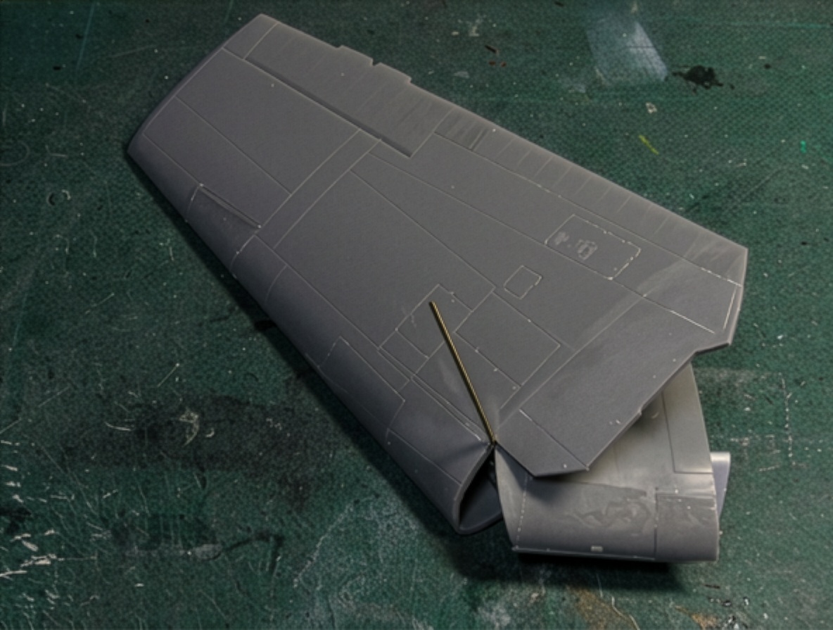
A folded F6F-5 Hellcat is visually impressive, but reproducing the mechanism in 1/48 scale requires more than simply cutting the wings and attaching them with a conventional hinge.
The mechanism had to satisfy three requirements:
The geometry had to remain as accurate as possible.
The wings had to remain rigid in both folded and extended positions.
The movement had to remain smooth and reliable.
Calculating the Wing-Folding Axis
The published wing-folding geometry from Model Airplane News was used as a starting point. However, I do not automatically trust secondary documentation such as drawings, descriptions or illustrations. Even apparently reliable drawings can contain inaccuracies.
For that reason, I decided to calculate the folding-axis angle mathematically.
The coordinate system uses the x-axis along the wingspan, the y-axis along the aircraft centerline and the z-axis vertically. The origin is located at the rotation axis.
When the wing folds, point P moves to Q and point R moves to S.
Points P and Q lie on one plane perpendicular to the rotation axis, while points R and S lie on another plane that is also perpendicular to the axis. During folding, the movement of P to Q forms an arc while the two planes remain parallel.
The equation of a plane is:
ax + by + cz + d = 0
The values of a, b and c define the slope of the plane, and the vector (a, b, c) is perpendicular to it.
By substituting the coordinates of points P, Q, R and S into the plane equation, a set of simultaneous equations can be obtained.
The equations are:
a x₁ + b y₁ + c z₁ + d = 0
a x₂ + b y₂ + c z₂ + d = 0
a x₃ + b y₃ + c z₃ + d′ = 0
a x₄ + b y₄ + c z₄ + d′ = 0
The unknown values are a, b, c, d and d′. What is required is the ratio between a, b and c, so a can initially be set to 1.
After eliminating d and d′, the values of b and c can be calculated.
The resulting equations are:
b = {(x₁-x₂)(z₃-z₄)-(x₃-x₄)(z₁-z₂)} / {(y₃-y₄)(z₁-z₂)-(y₁-y₂)(z₃-z₄)}
c = {(x₁-x₂)(y₃-y₄)-(x₃-x₄)(y₁-y₂)} / {(y₁-y₂)(z₃-z₄)-(y₃-y₄)(z₁-z₂)}
The required coordinate values can be obtained through direct measurement.
Using Excel makes the calculation relatively straightforward. The projection angles of the rotation axis in the zx and zy planes are:
θx = tan⁻¹(a/c)
θy = tan⁻¹(b/c)
For the 1/48 scale model, the folded wingspan is approximately 65 mm (2.54 in), while the height of the wingtip above the upper wing surface is approximately 30 mm (1.2 in).
The wing inclination in the folded position is approximately 55°, with a dihedral angle of 7.5°.
Using these measurements, the calculated values were:
θx = 28.5°
θy = 26.3°
For modeling purposes, the projection angle of the main spar plane is particularly useful.
The relationship is:
tan θw = cos θy × tan θx
which gives:
θw = 25.9°
Interestingly, the final calculation showed that the Model Airplane News drawings were correct.
So perhaps all that mathematical work was unnecessary—but it did provide a way to independently verify the published geometry.
More importantly, the same calculation method can potentially be applied to other aircraft with folding wings, including the Grumman F4F Wildcat, Grumman TBF Avenger and Fairey Firefly.
Building the Wing Hinges
Maintaining accurate hinge geometry required several modeling tricks.
The real aircraft uses two hinges attached to the wing post. Reproducing each hinge as a separate component in 1/48 scale would make accurate alignment extremely difficult.
Instead, the upper and lower hinge pair was treated as a single structural unit. The hinge pair and the main body were also integrated into one assembly.
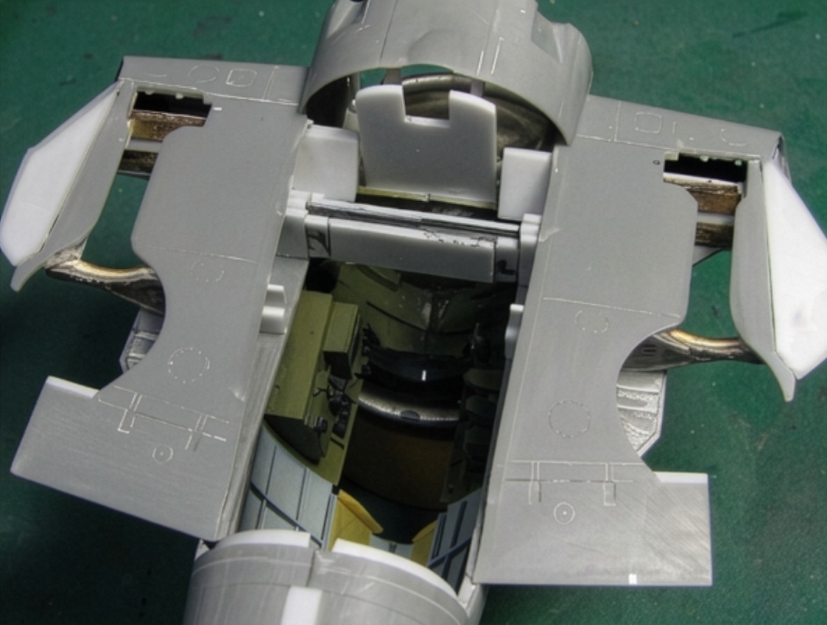
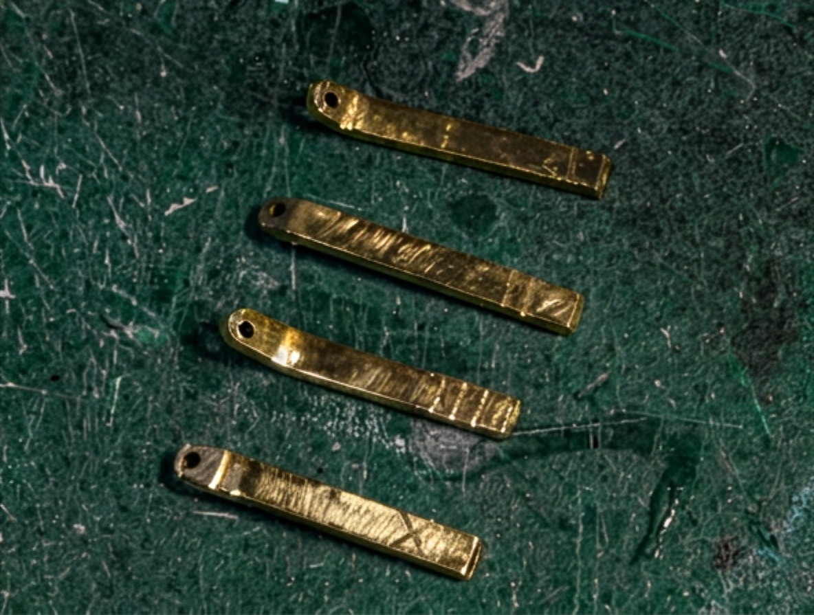
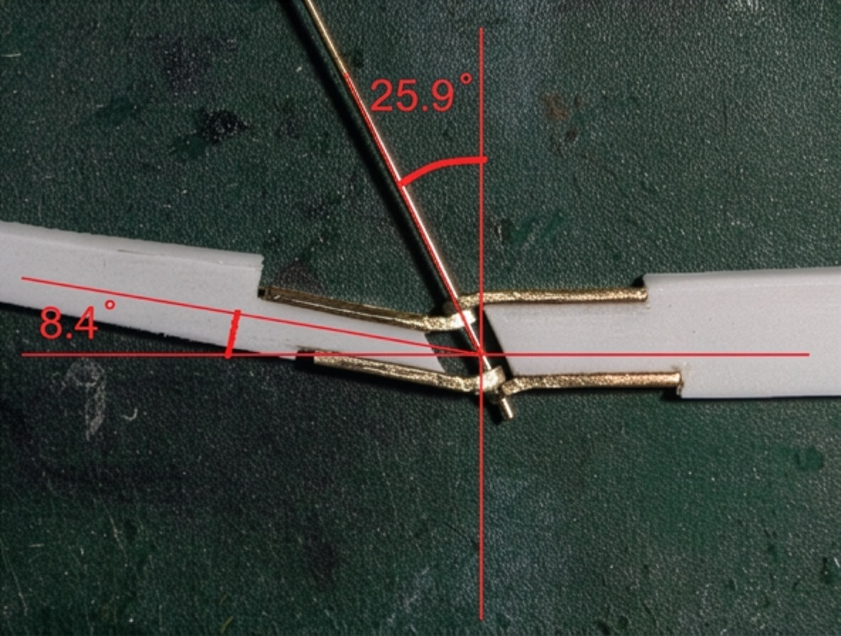
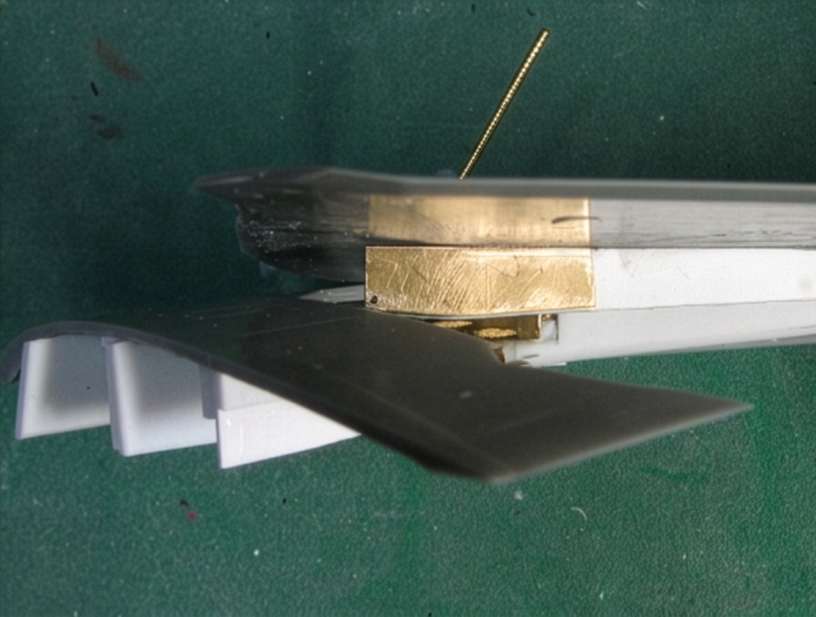
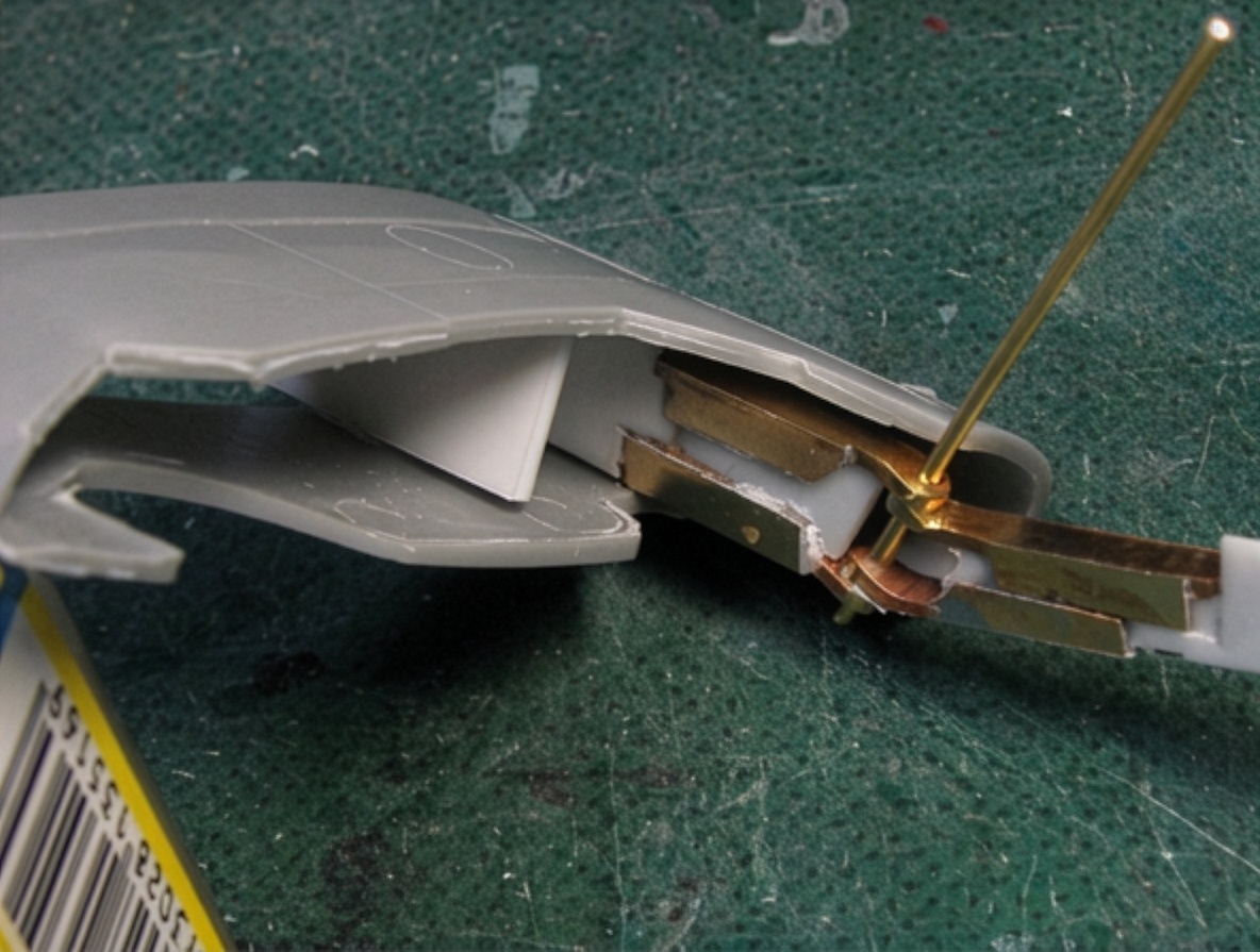
The basic hinge structure consists of a brass rod passing through four drilled brass square rods. The angle of this brass shaft is critical.
The outer and inner main beams were then attached to the brass rods using epoxy glue.
The main beams were made from 1.2 mm (0.05 in) plastic sheet, and the hinge-axis inclination was set to 25.9° according to the calculations.
One important lesson was that small errors in drilling and alignment can be absorbed by the adhesive gaps.
Hand-drilling inevitably introduces small errors in hole position and angle. If the connection between the brass rod and the plastic reinforcement allows a small gap that can be filled with adhesive, the final hinge alignment can still be corrected.
If the components are glued tightly together without any allowance for adjustment, achieving accurate alignment becomes much more difficult.
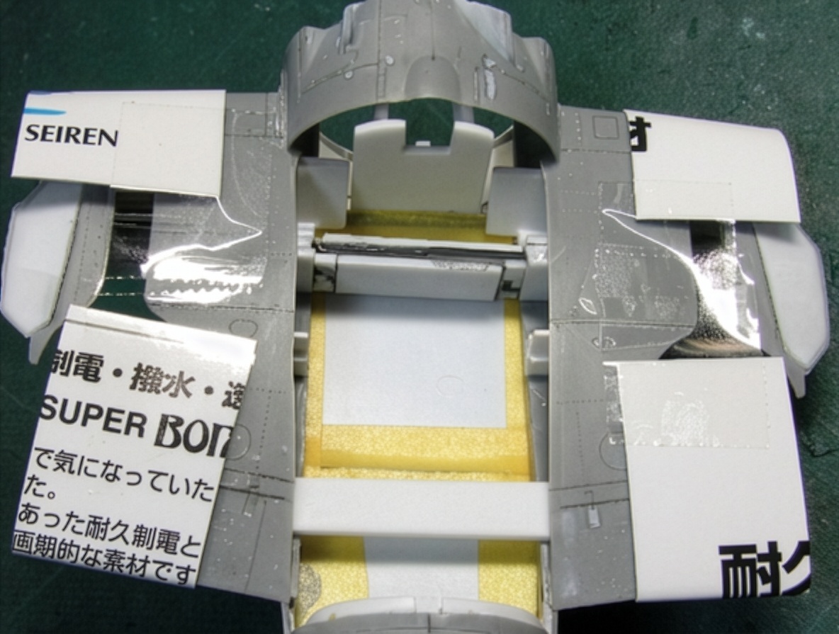
The upper inner and outer flaps were carefully connected with Scotch tape while maintaining the correct dihedral.
The completed hinge and brass-rod assembly was then attached to the flap structure, with particular attention paid to the spar-web angle.
The lower wing components were glued only after the hinge alignment had been established.
The resulting hinge is not an exact miniature reproduction of the real aircraft mechanism. At 1/48 scale, some compromises are unavoidable.
The Wing Connecting Member
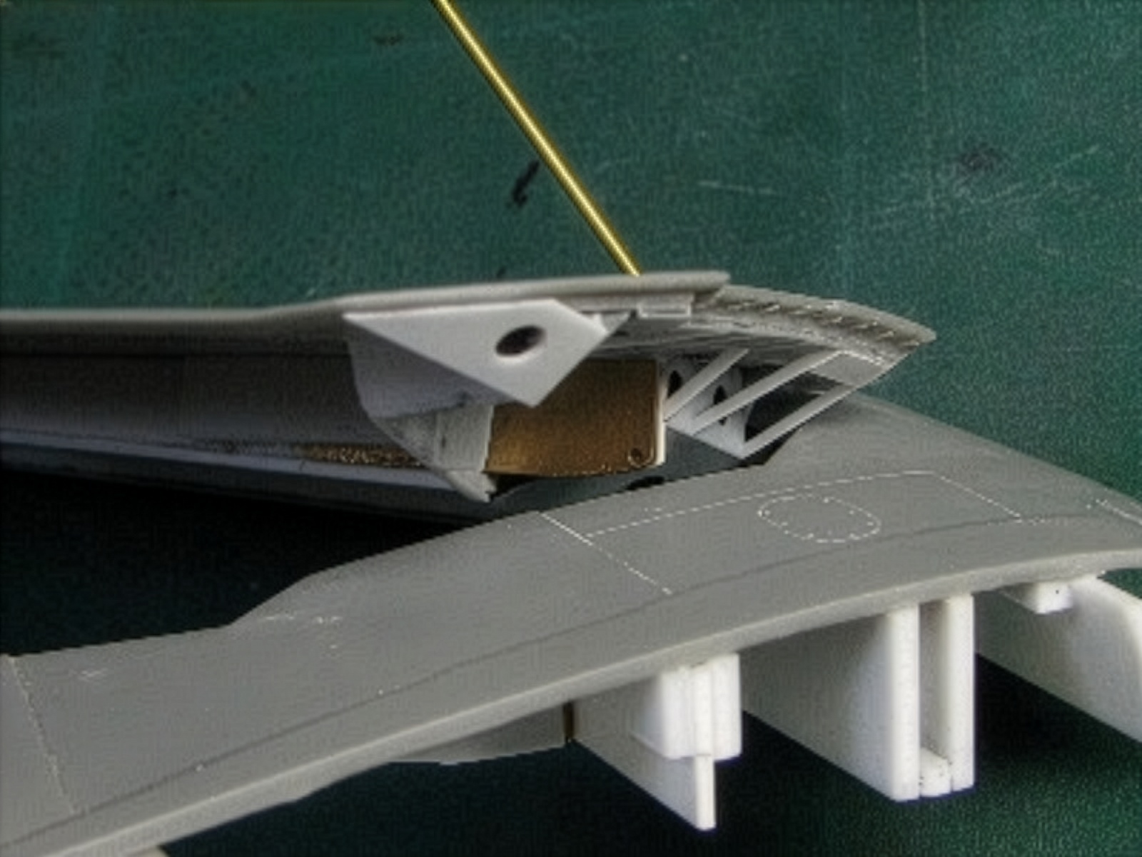
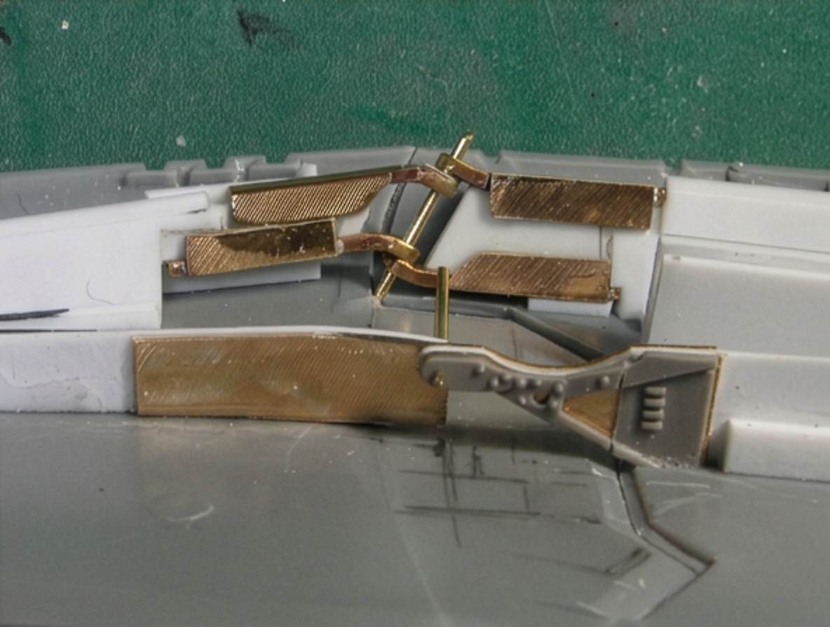
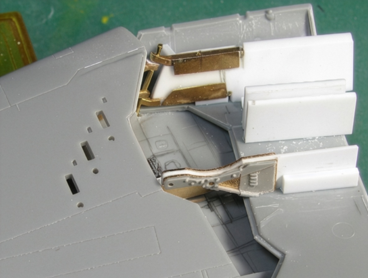
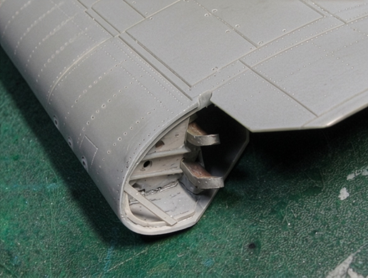
The outer wing of the F6F-5 Hellcat is connected to the inner wing through a pin located on the secondary strut.
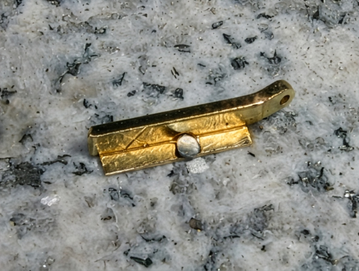
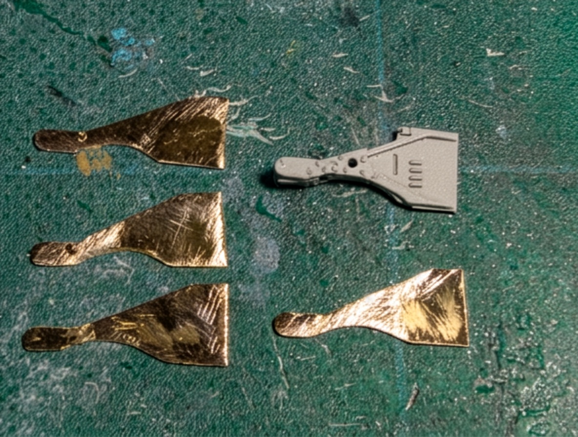
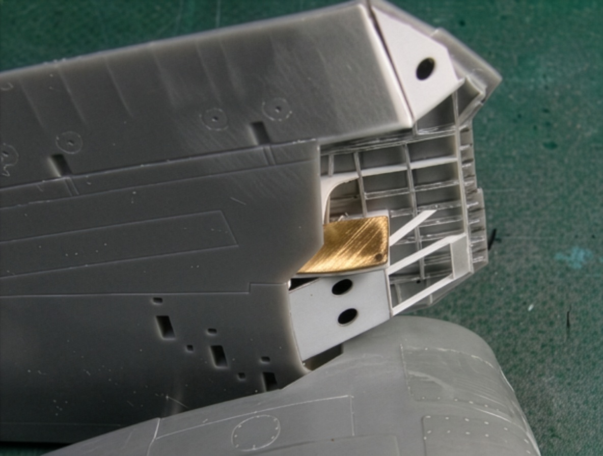
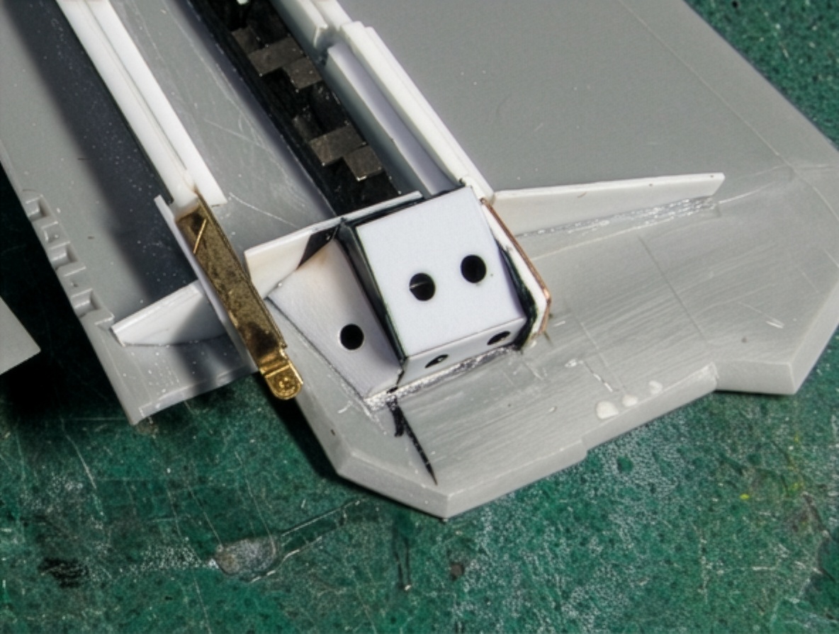
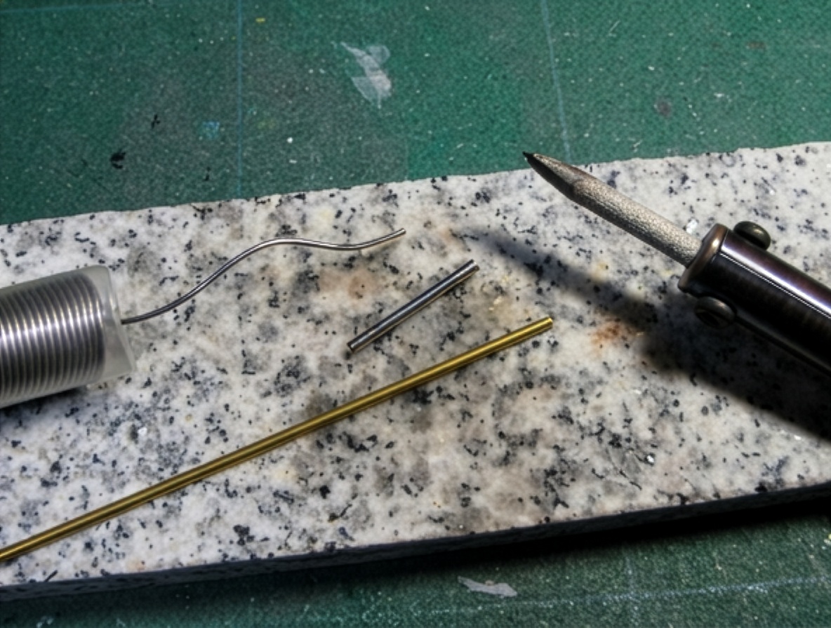
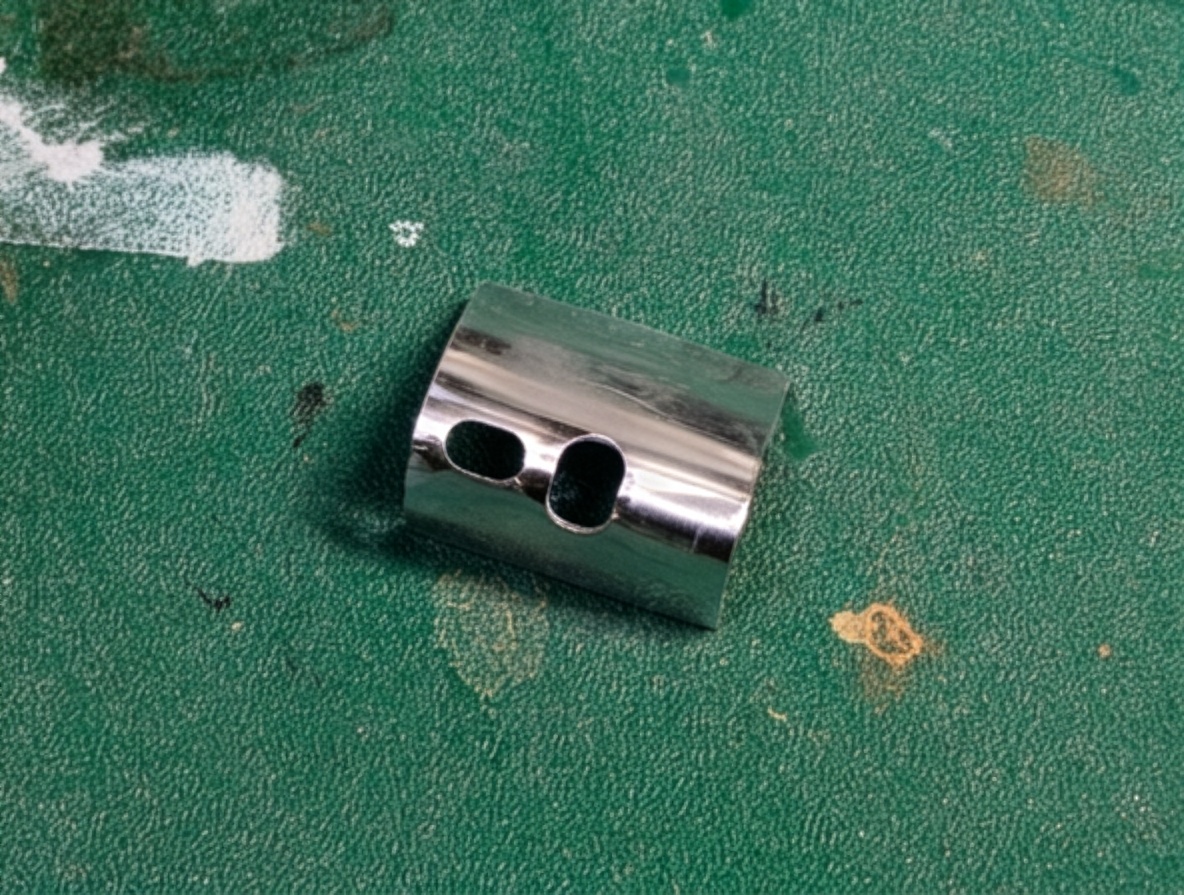
I reproduced this mechanism in simplified form using brass sheet.
Each brass member was attached to the inner and outer plastic structures and drilled to accept the connecting pin.
The two sections were joined with a brass pin and then secured to the upper wing structure.
Initially, I expected this part to be easier than the main hinge. In reality, it became one of the most difficult parts of the entire folding-wing mechanism.
The reason was clearance.
The real aircraft’s wing-folding structure was designed with very small clearances between the various components. At 1/48 scale, it is impossible to reproduce every component at mathematically exact scale while also maintaining sufficient structural strength.
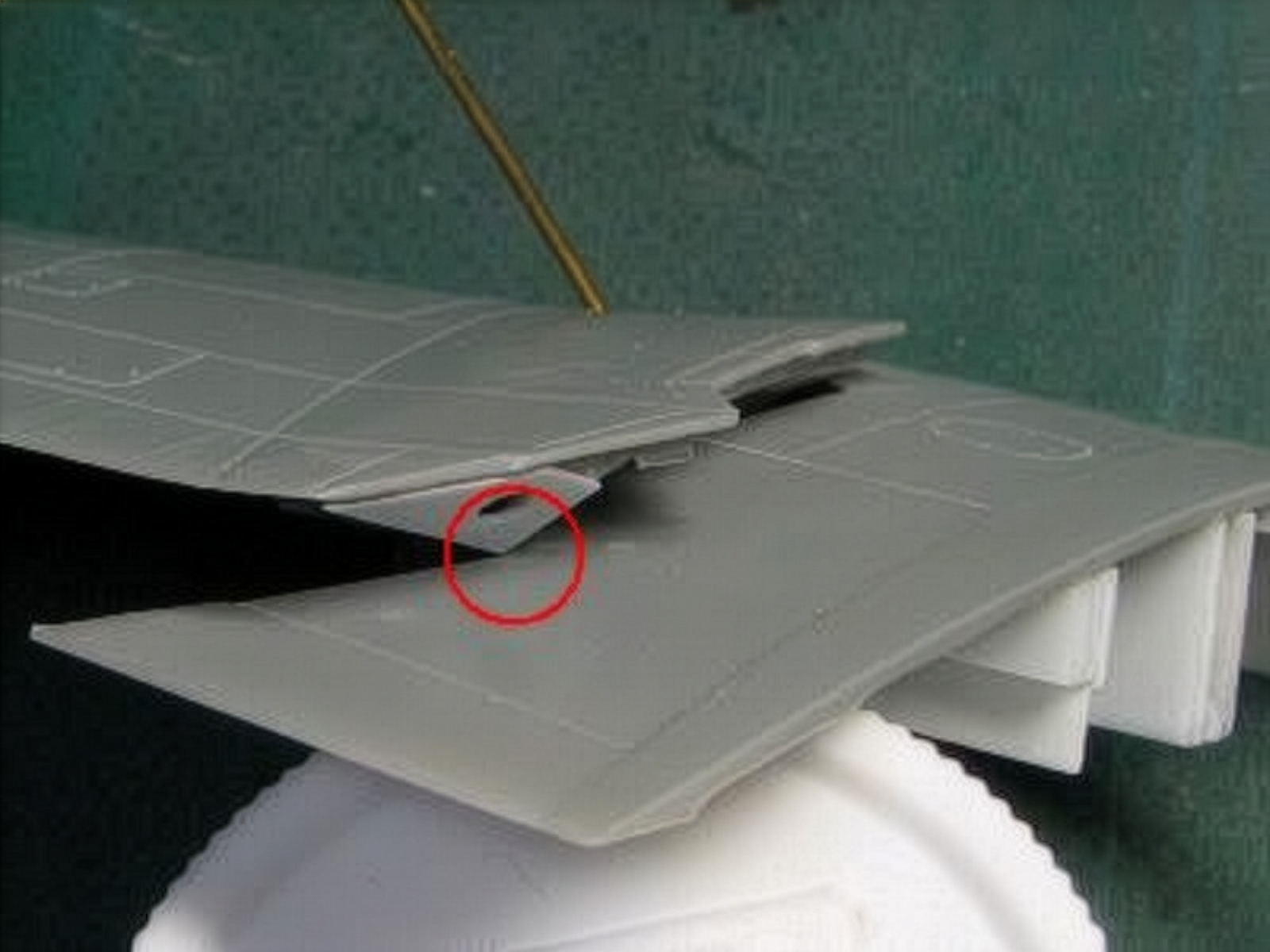
The connecting members therefore interfered with the wing cut line.
Their exact position—high and low, left and right, forward and rearward—had to be determined through repeated trial and error. The shape of the wing cut line also required adjustment.
Three or four rounds of testing were necessary before the mechanism could move correctly without interference.
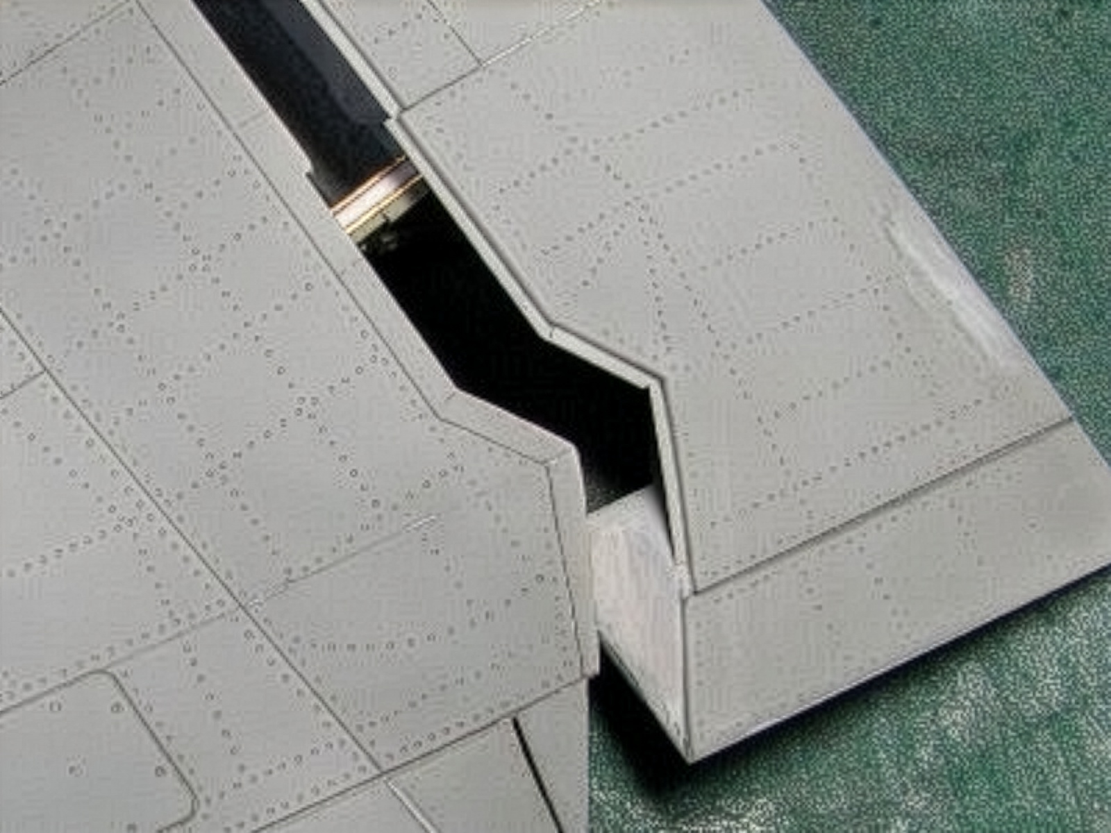
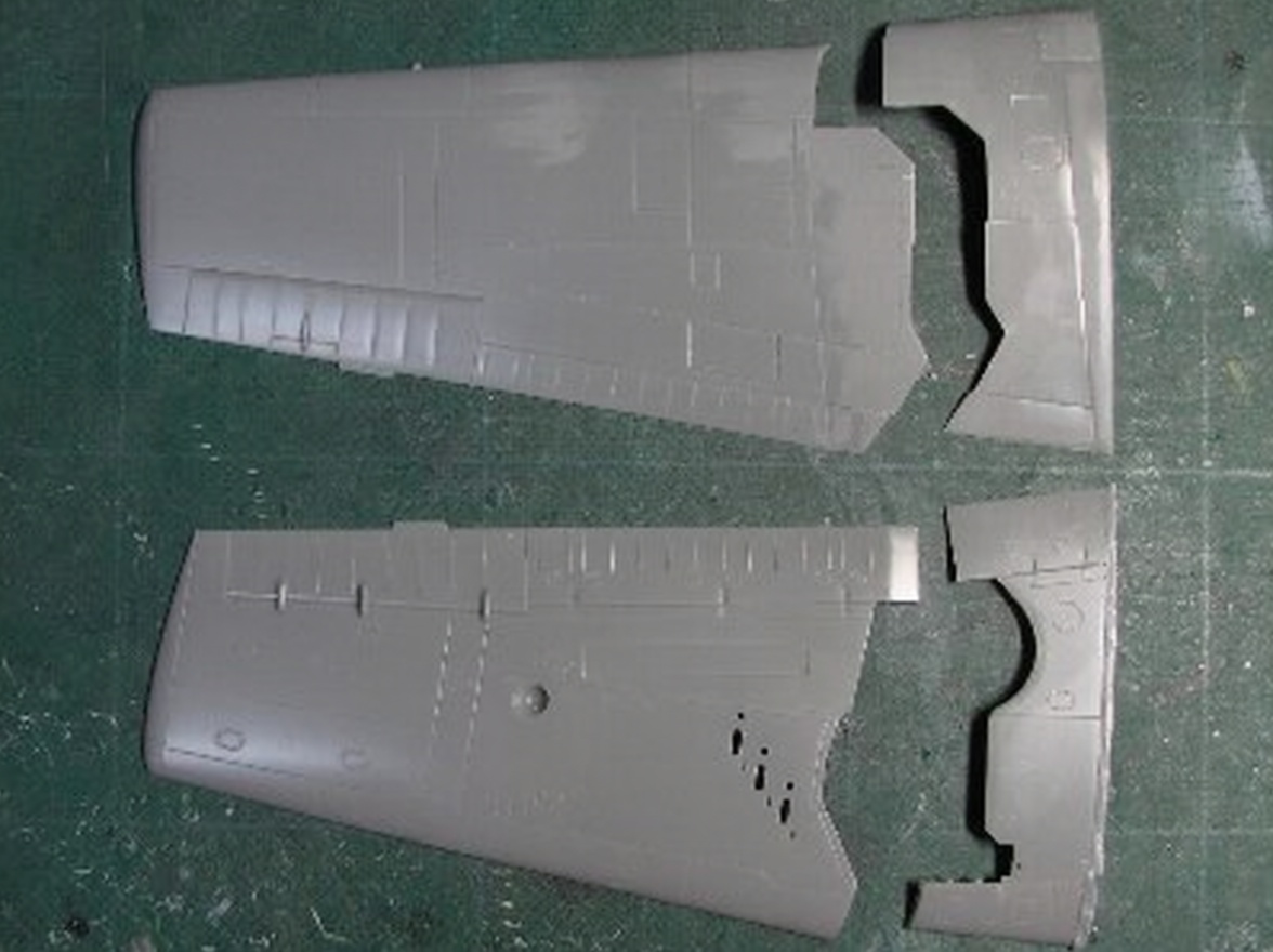
The Upper Wing Parting Line
Another difficult area was the upper wing parting line.
The outer wing rotates through a relatively shallow angle during folding. As a result, the leading edge of the dividing line becomes extremely thin.
Reproducing this geometry accurately in a scale model is difficult because there is very little material available to work with while still maintaining sufficient strength.
Hellcat Wing Specifications
The main wing dimensions used as reference for the model were:
Wingspan: 42 ft 10 in
Wingspan folded: 16 ft 2 in
Airfoil: NACA 23000 series
Chord ratio at fuselage center: 14.65%
Chord ratio at station 252: 9%
Chord at fuselage center: 10 ft 7 in
Chord at station 252: 5 ft 3 in
Angle of incidence: 0°
Washout: 0°
Inner-wing dihedral: 0°
Outer-wing dihedral: 7.5°
Horizontal flap span: 16 ft 6 in
Horizontal flap angle of incidence: 1.5°
Vertical-fin setting: 0°
Tail-fin thickness ratio: 11%
Refining the Cowling Again
I was still not satisfied with the first corrected cowling.
So I purchased another kit—the third kit used during this project—and started the cowling again.
The front section was retained, while the new side section was divided into four pieces and reassembled with four styrene reinforcement strips.
The upper strip measured approximately 2 mm (0.08 in) at the front and 1.5 mm (0.06 in) at the rear.
The side strip was approximately 0.5 mm (0.02 in) at the front and 1 mm (0.04 in) at the rear.
The lower strip was approximately 2 mm (0.08 in) at the front and 2.5 mm (0.1 in) at the rear.
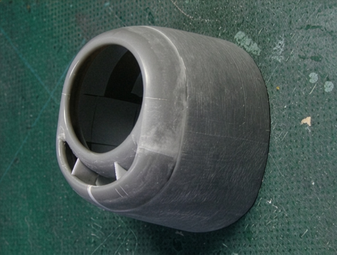
The completed cowling was considerably larger, with the outer perimeter at the rear increased by approximately 6 mm (0.24 in) overall.
This final correction gave the cowling the broad, heavy appearance that is so characteristic of the real F6F-5 Hellcat.
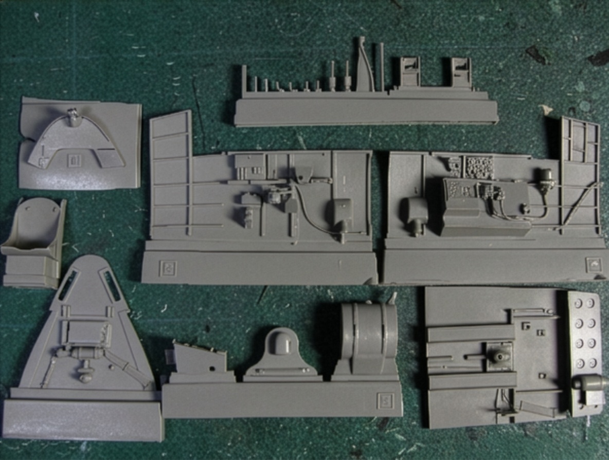
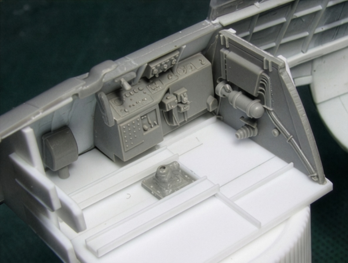
Cockpit
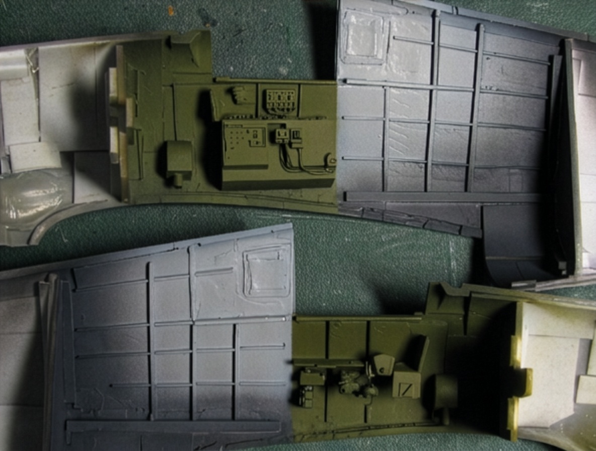
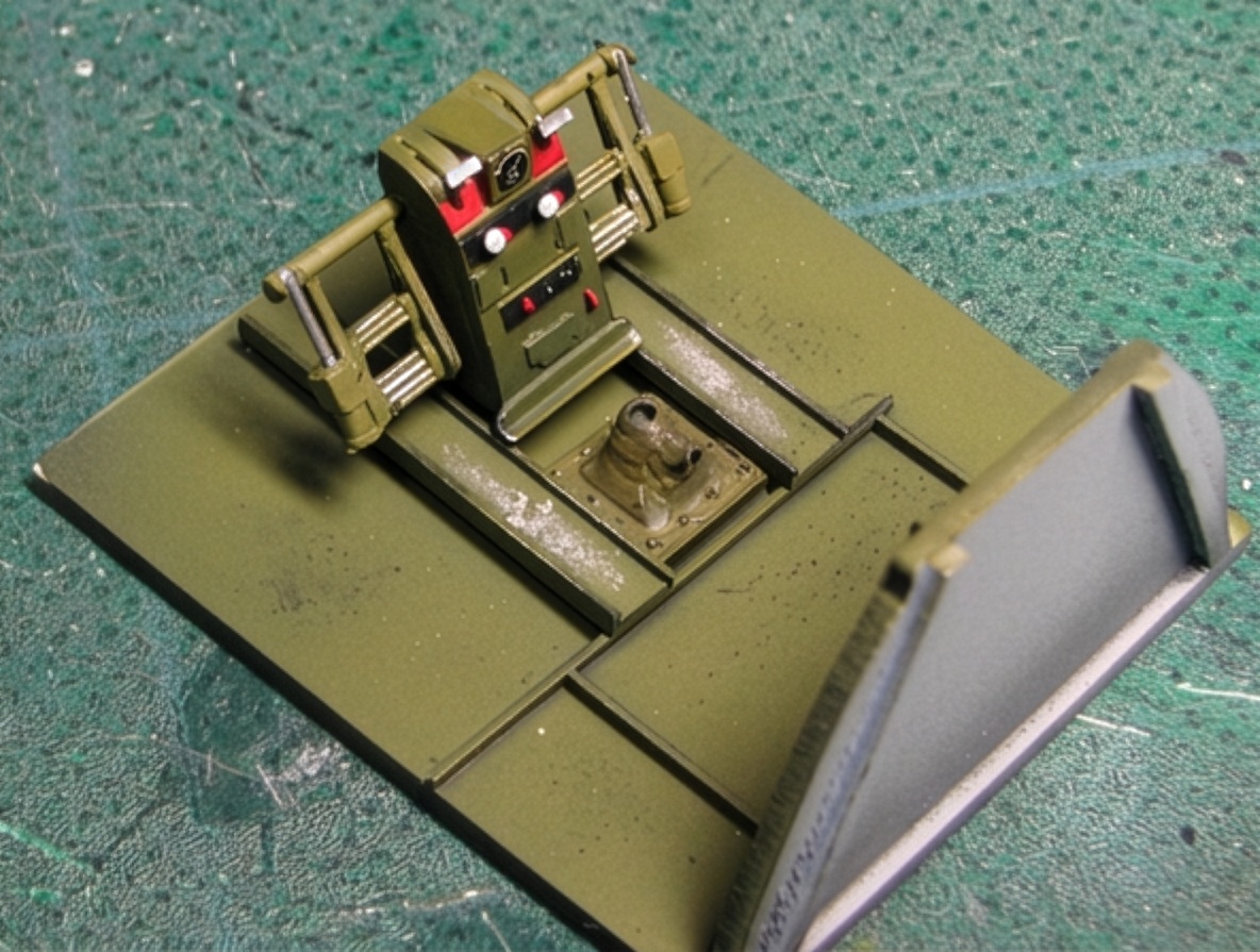
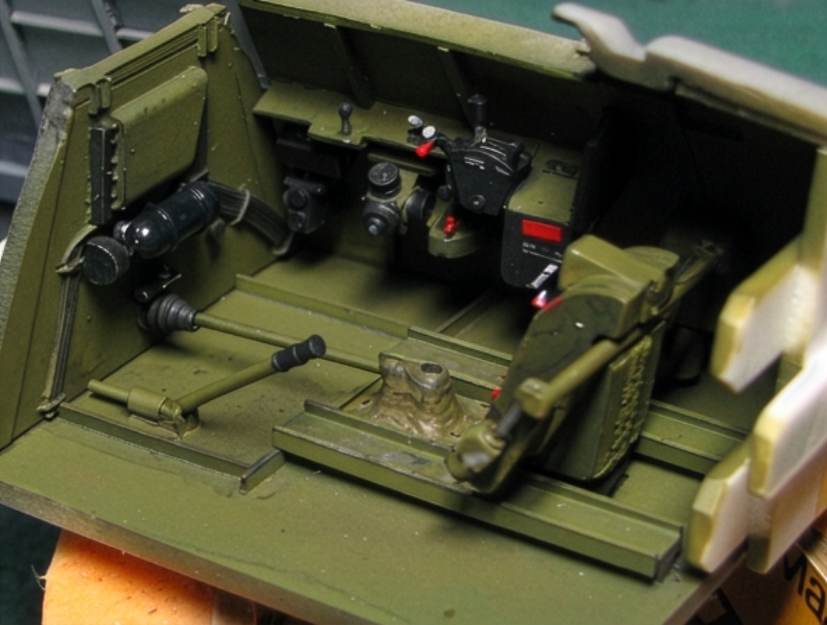
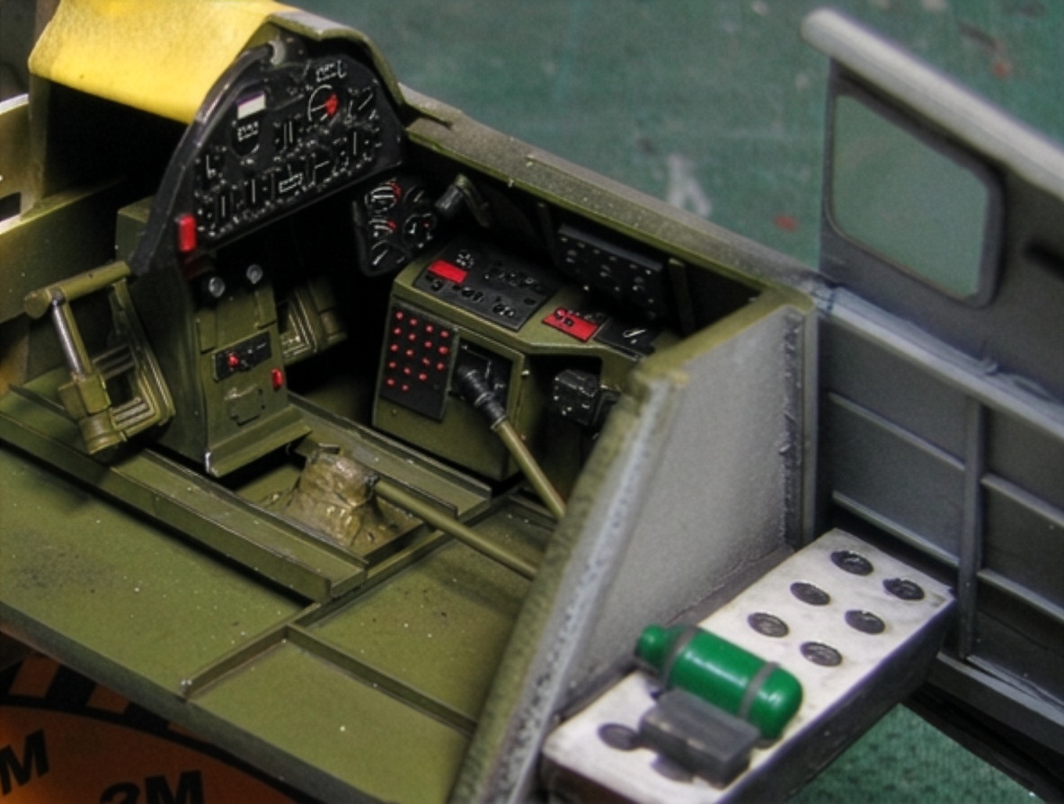
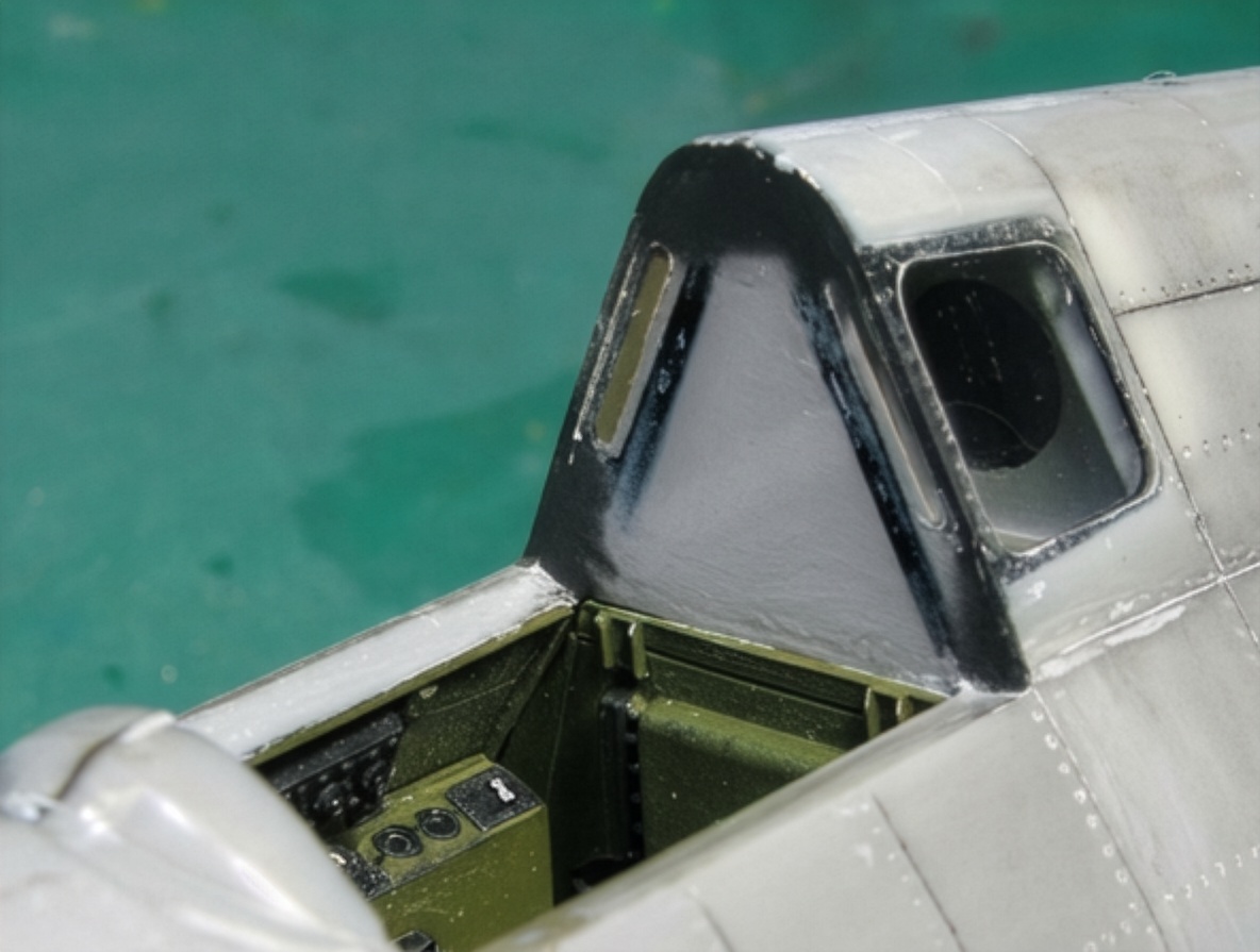
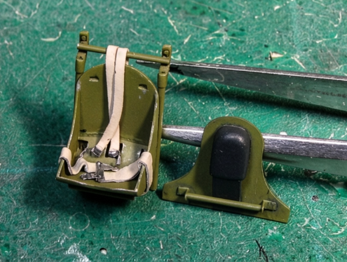
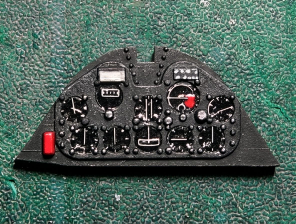
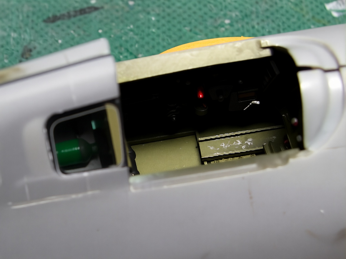
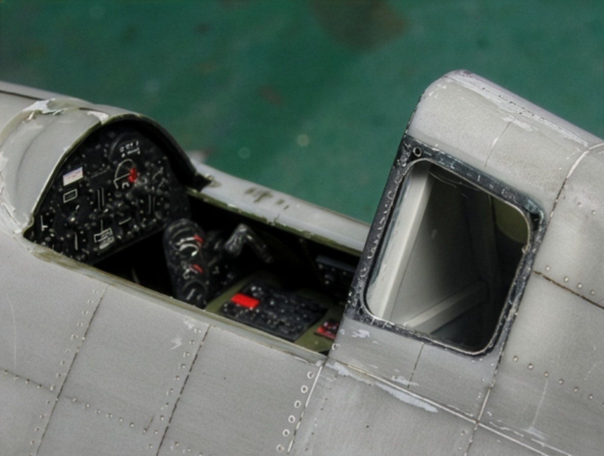
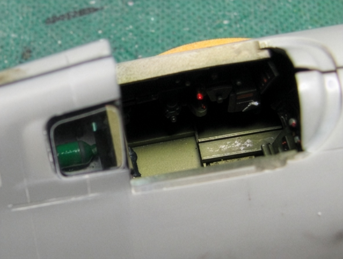
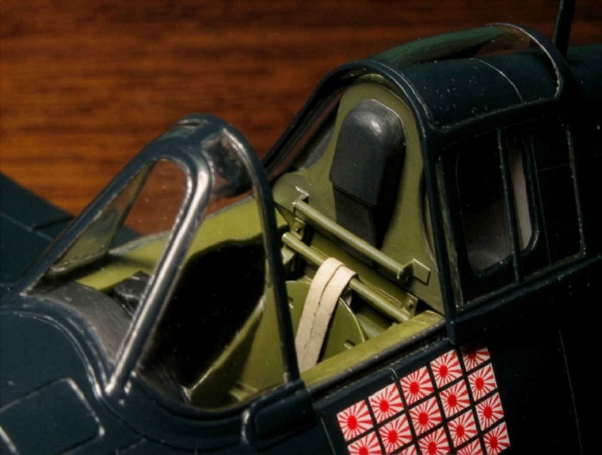
The cockpit interior was painted green.
The rear fuselage was finished in light gray. I did not know the exact color, so I used FS 36495 as the main reference color.
Joining the Corrected Fuselage
Because the fuselage halves had previously been stretched and bent to correct the external shape, the left and right sides were no longer perfectly symmetrical.
This made the final assembly particularly sensitive to distortion.
The upper rear fuselage was initially joined using plastic cement.
After carefully checking the structure and confirming that no distortion had developed, the nose and tail-fin sections were joined with CA glue.
The fuselage surface was subsequently refined and blended.
The junction between the cowling and forward fuselage was deliberately treated according to the structural lines visible in the reference drawings rather than simply being made into a completely smooth transition.
Engine and Cowling Interior
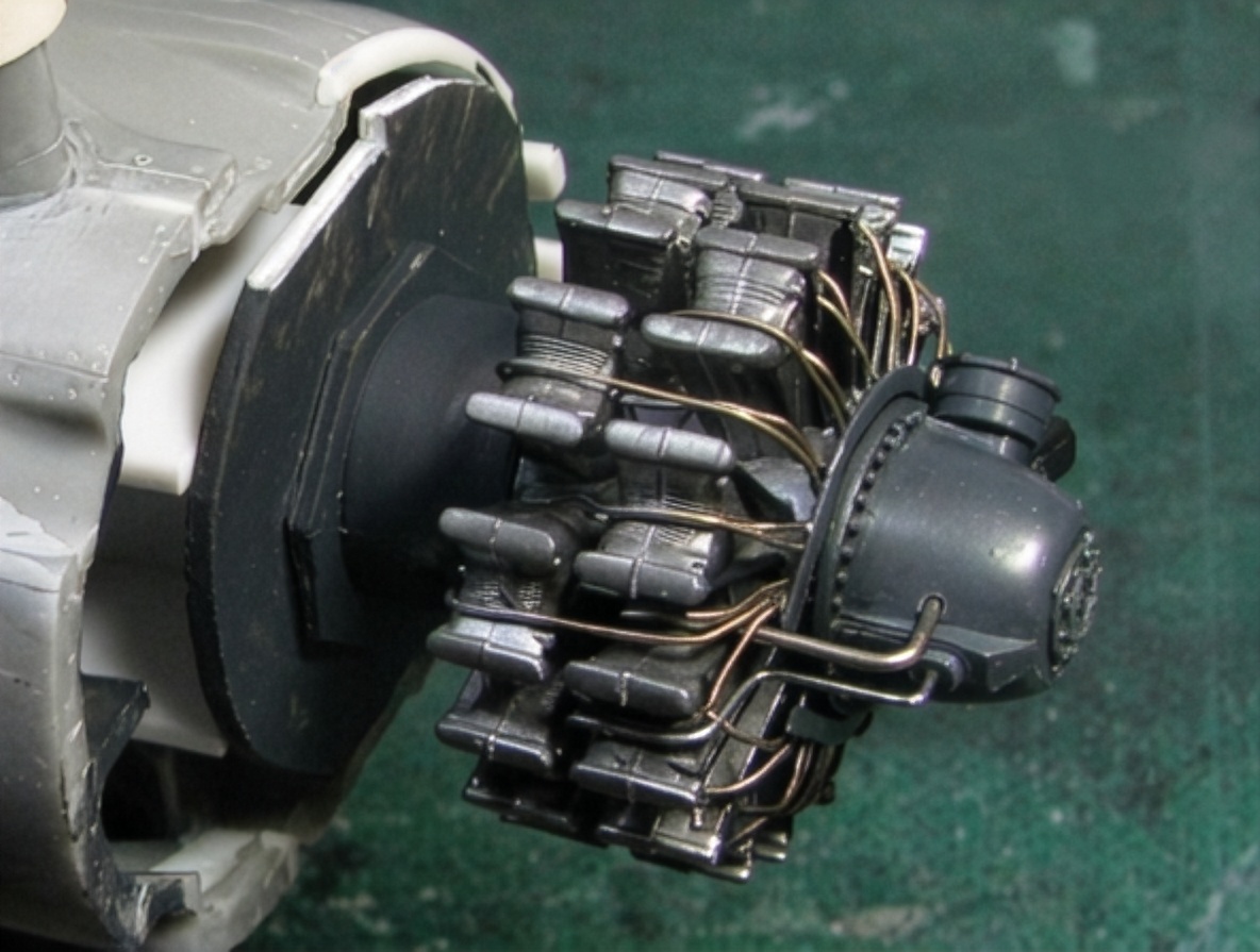
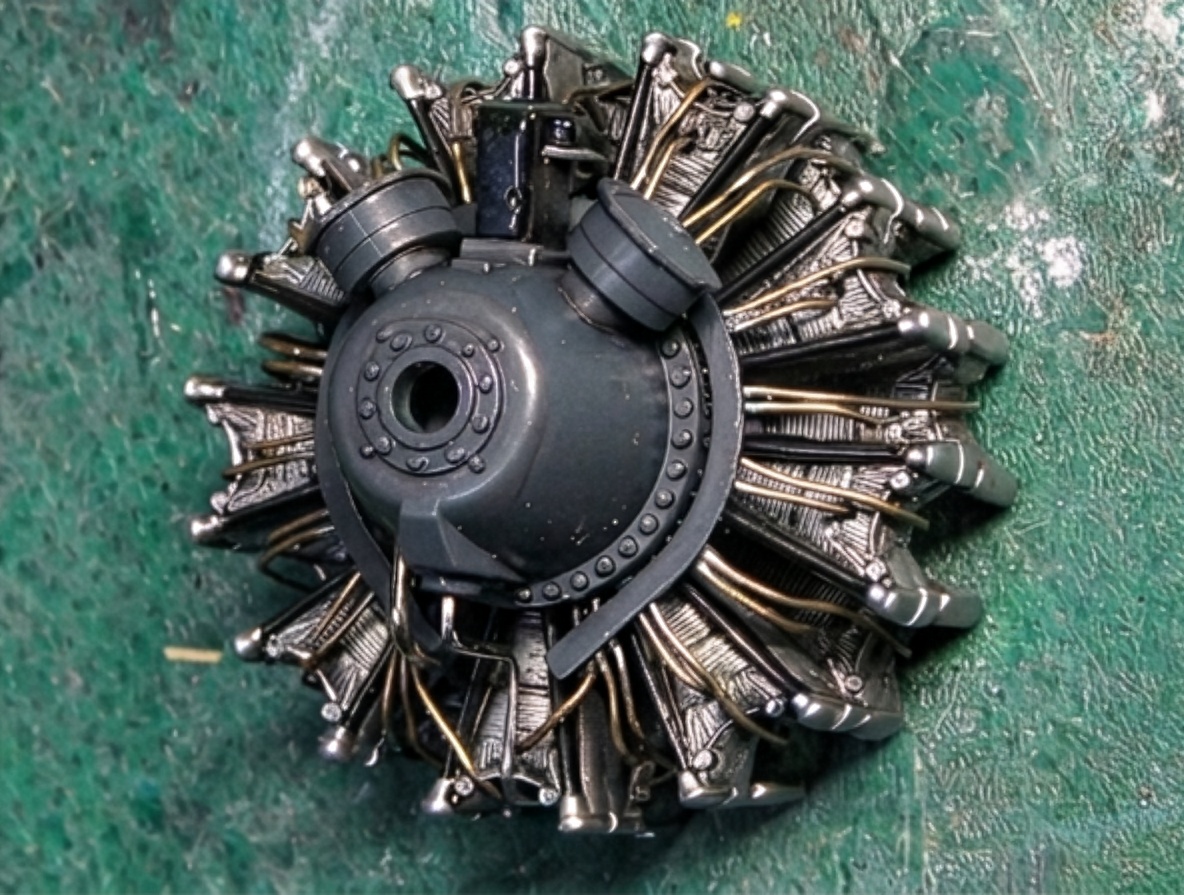
The inside of the F6F-5 Hellcat cowling was painted Yellow Zinc Chromate to make the internal structure and details easier to see.
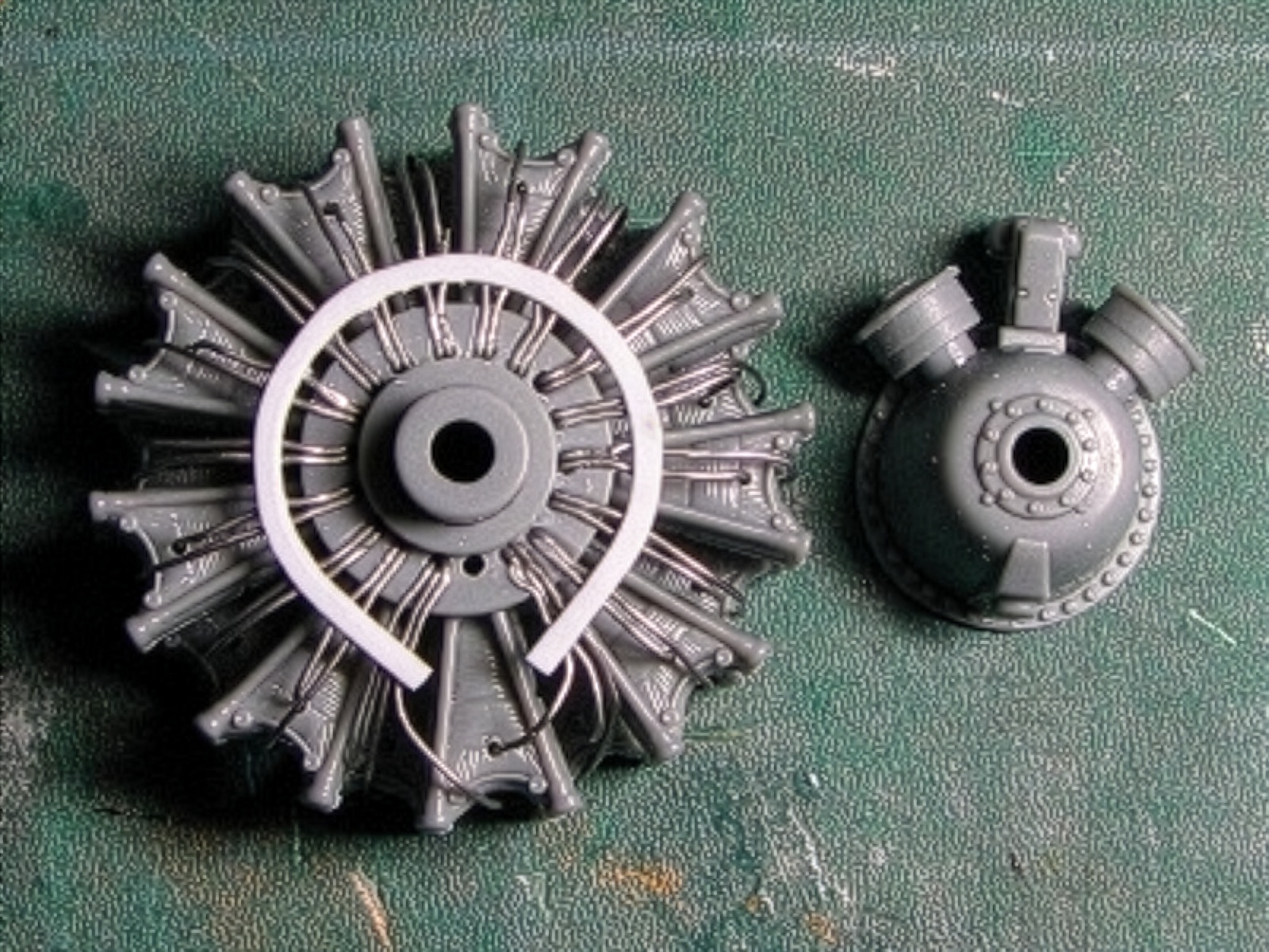
The engine is a Pratt & Whitney R-2800-10W Double Wasp taken from the Tamiya P-47 kit.
The Tamiya Double Wasp offers excellent detail, although its diameter is slightly smaller than required.
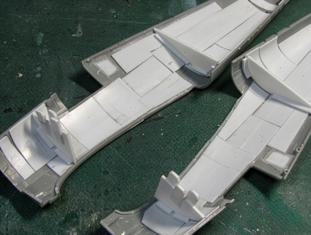
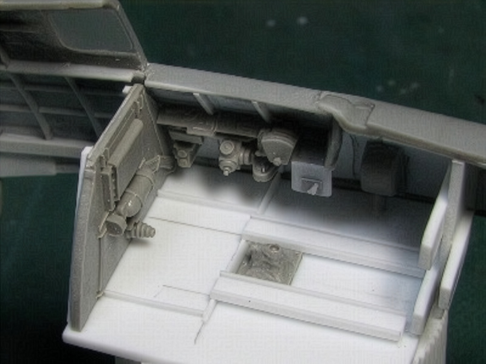
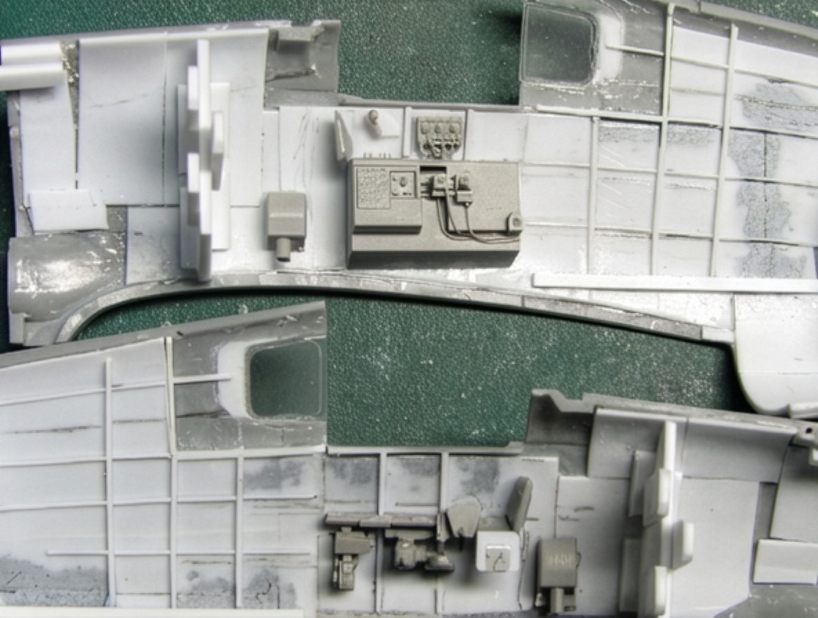
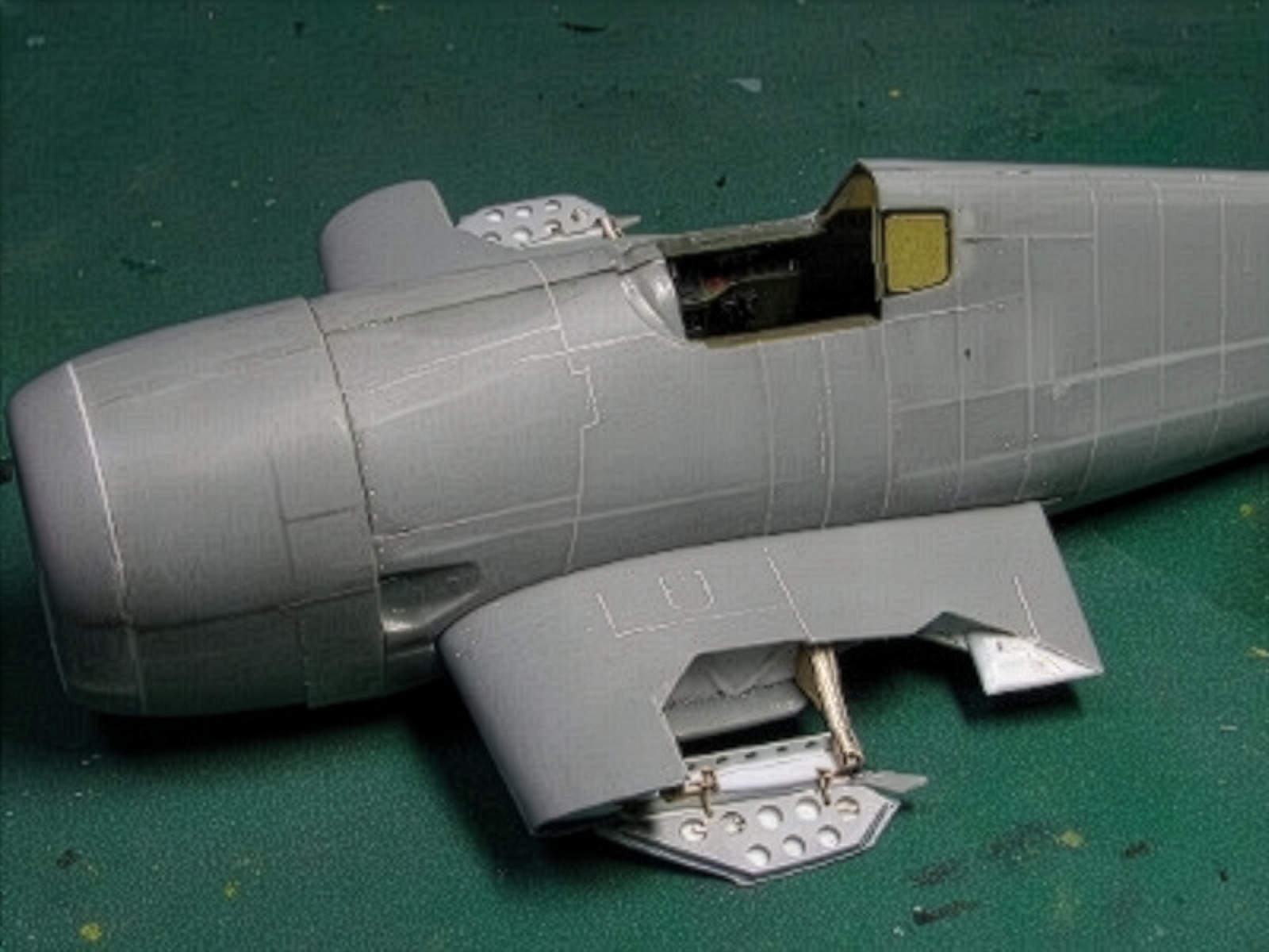
Main Landing Gear Bay
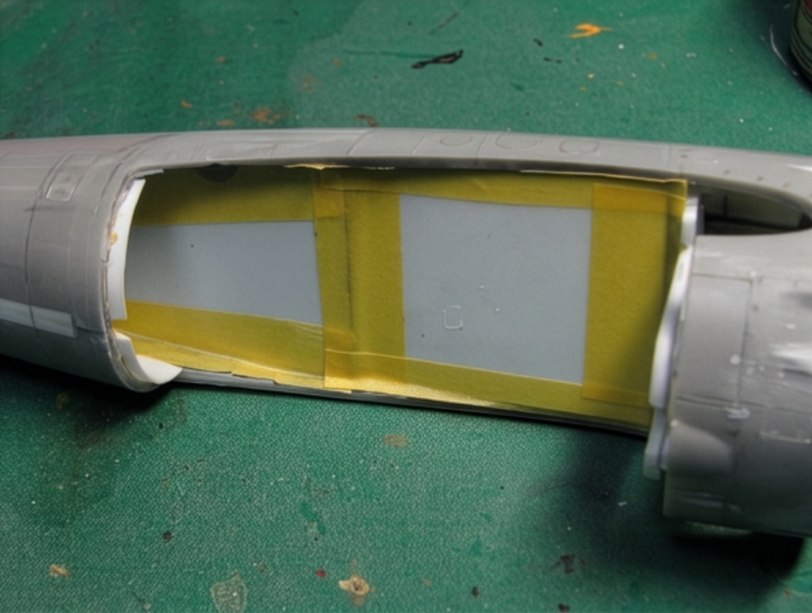
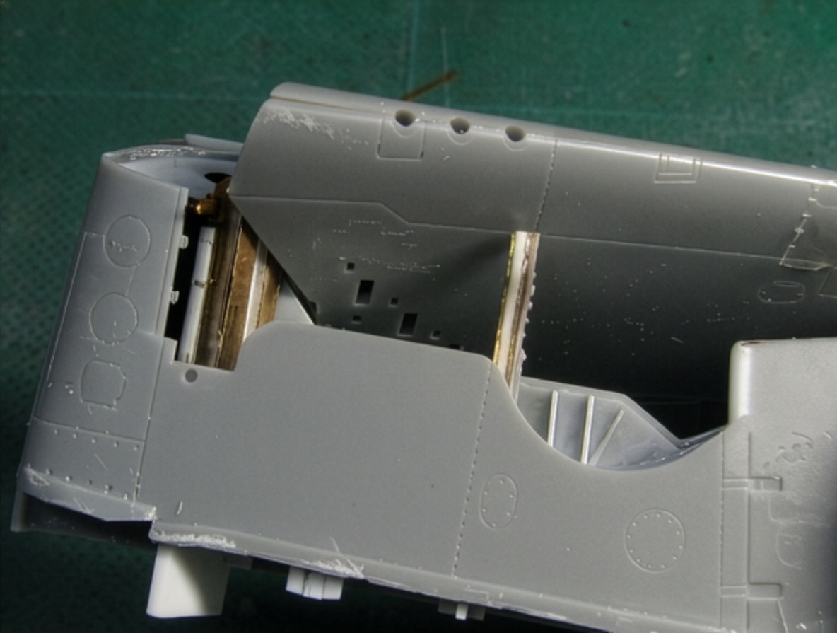
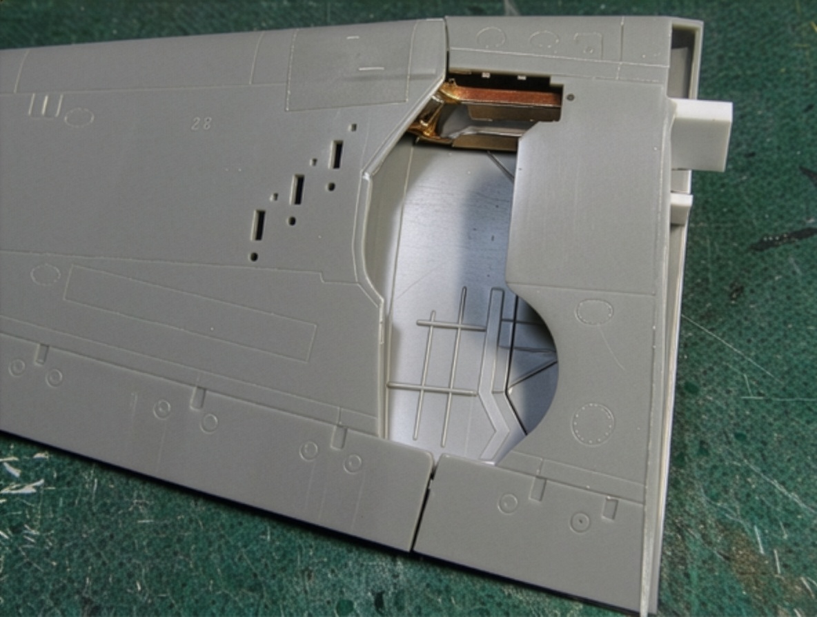
The landing-gear bay presented another major challenge.
I had purchased the Aires resin detail set, but it could not be used because of the folding-wing mechanism.
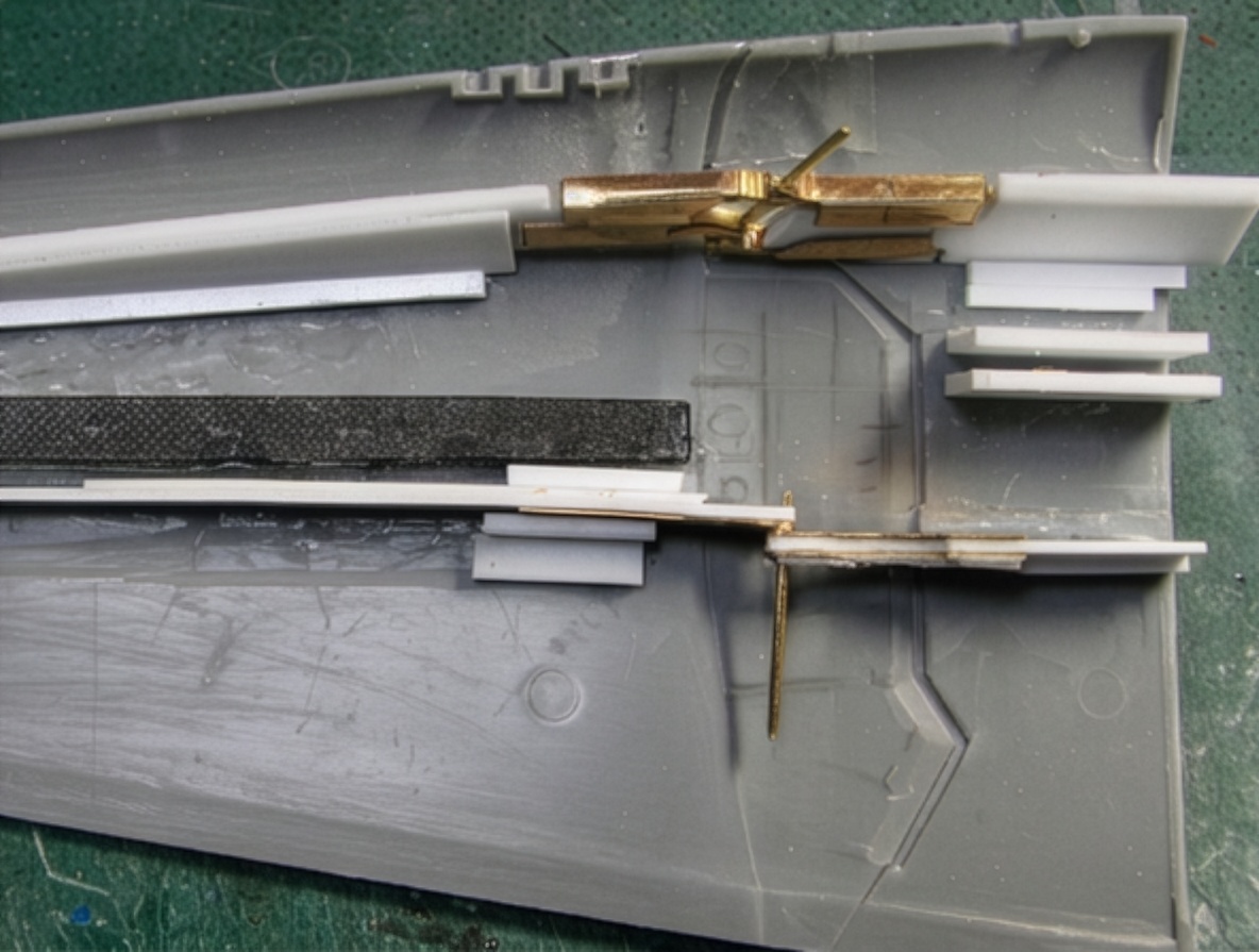
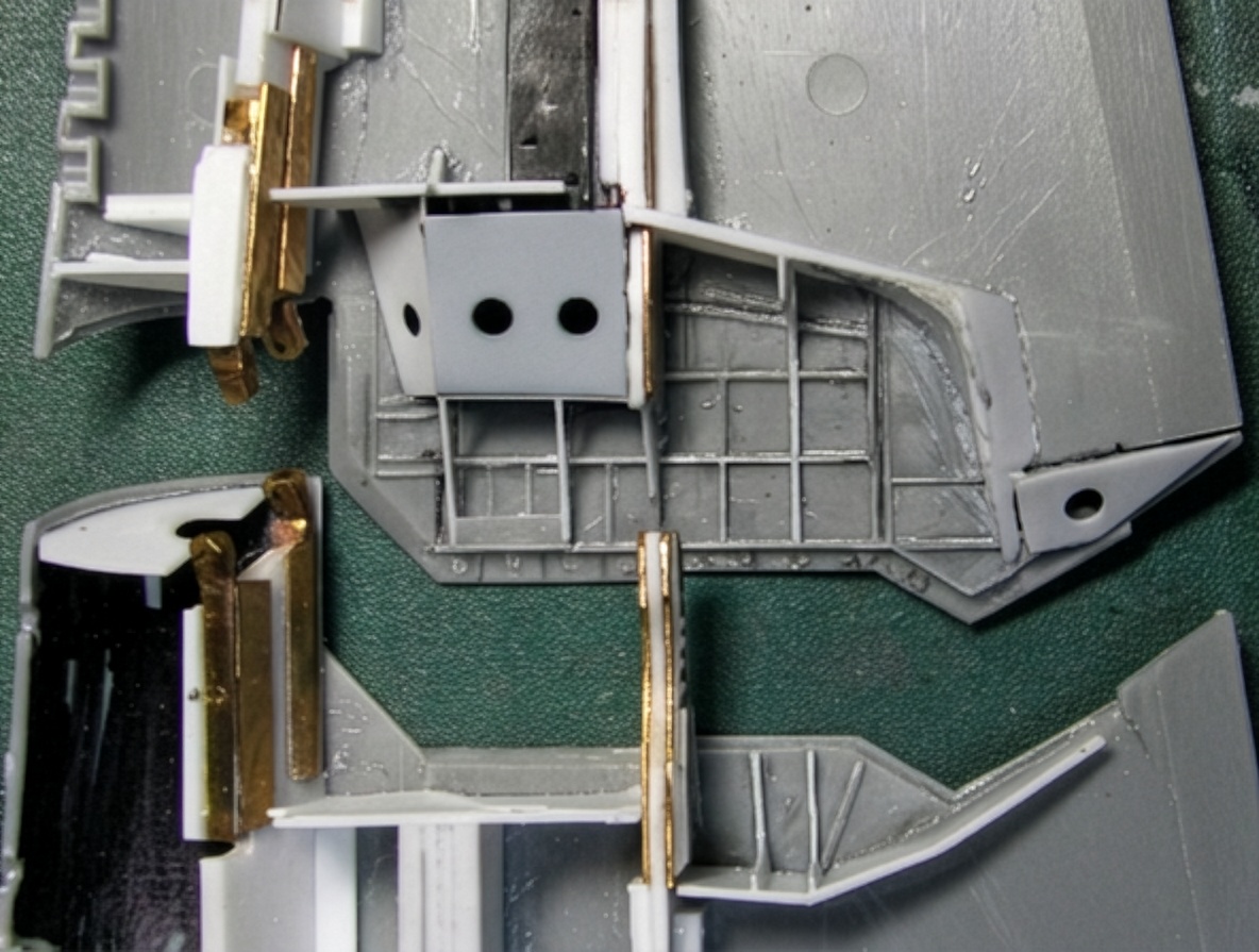
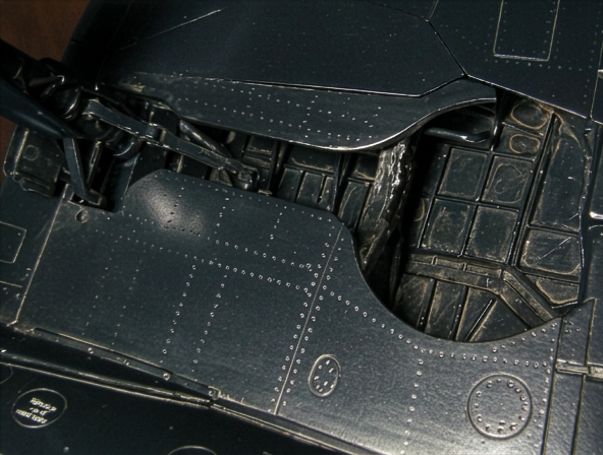
The entire gear-bay structure therefore had to be scratch-built.
A completely accurate reproduction was not possible for several reasons.
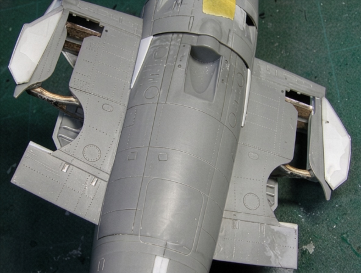
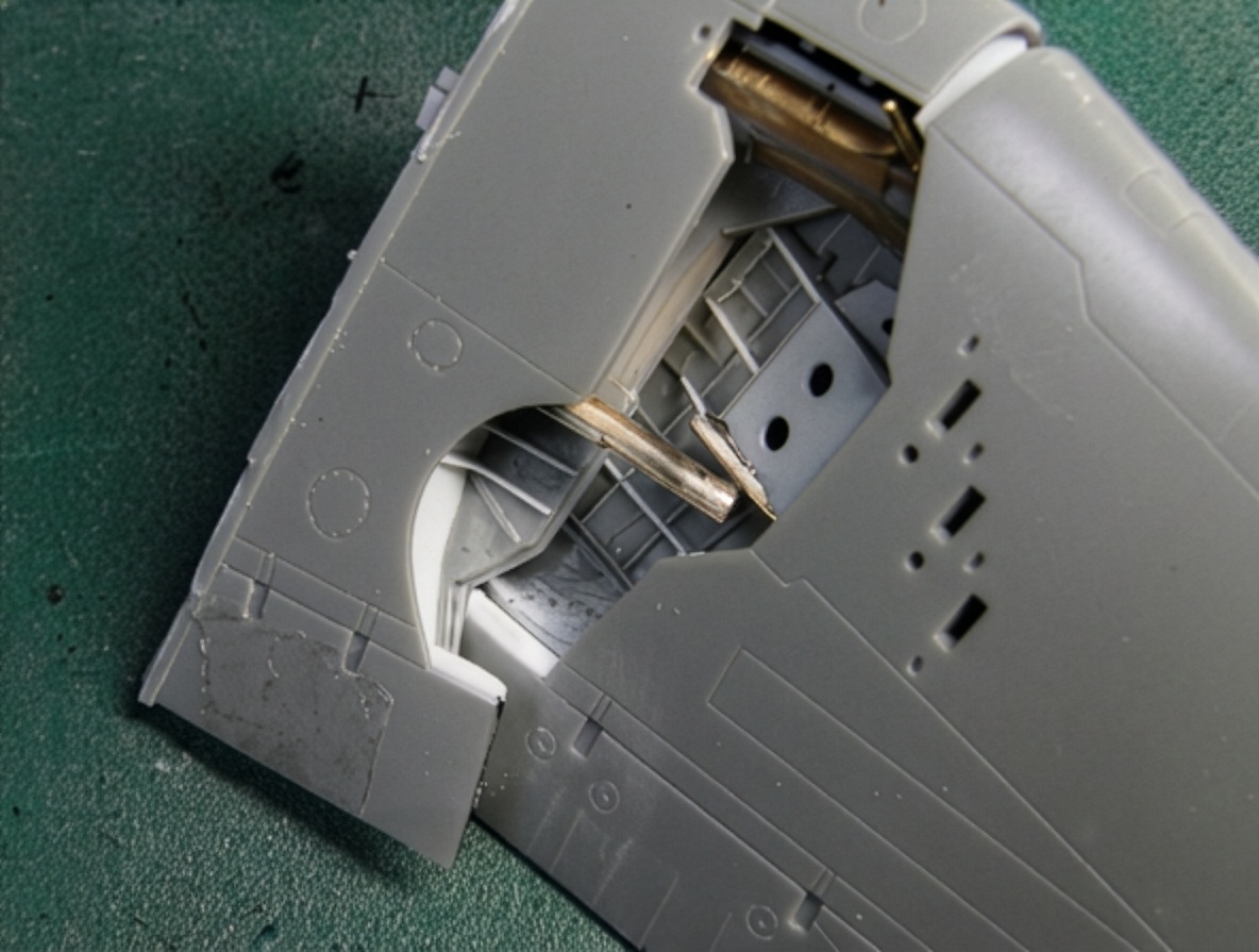
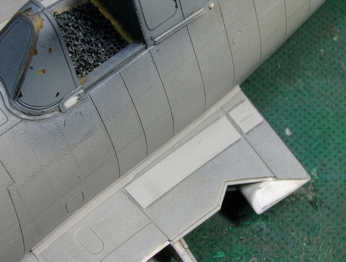
First, the wing parting line passes through the center of the landing-gear area.
Second, the position of the connecting member differs from the real aircraft and interferes with the wing-cut line.
Third, the geometry of the kit’s wing cut line and gear-bay opening is slightly incorrect.
Finally, the roof of the gear case could not be made thin enough to reproduce the required rivet detail without compromising the structure.
The complicated shape of the wing cut line becomes much easier to understand once the wing is actually moved. Every angle and line has a mechanical purpose.
After completing the gear bay, the upper and lower wing sections were joined.
As previously noted, the real aircraft maintains a relatively constant absolute thickness through the center wing area. To reproduce this, a wedge-shaped strip was inserted into the leading-edge joint, increasing the thickness at the folding line by approximately 0.5 mm (0.02 in).
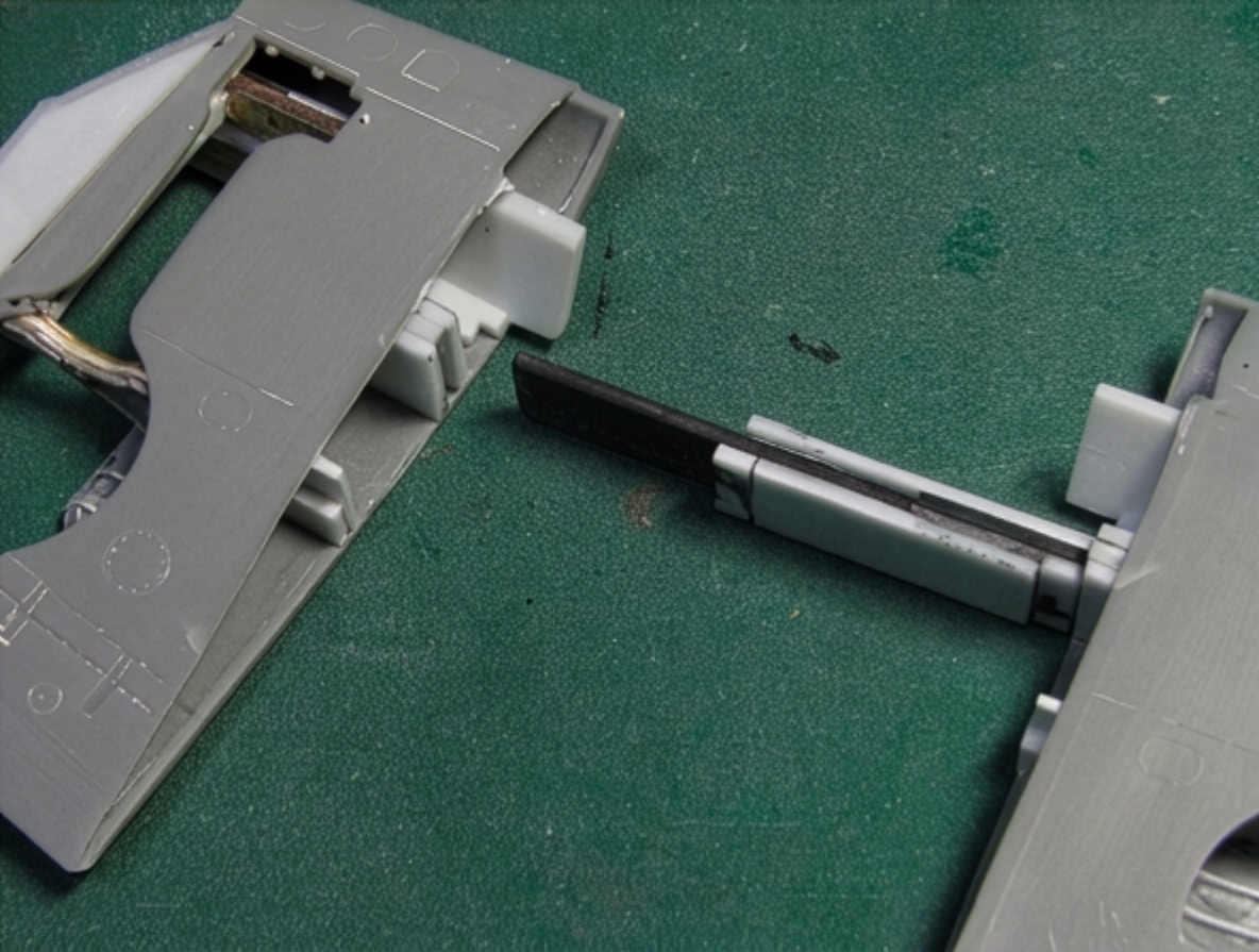
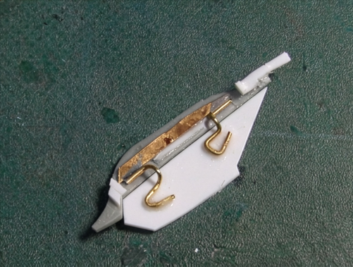
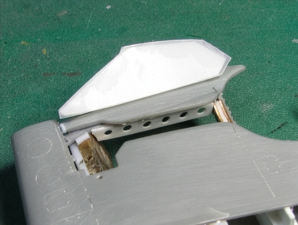
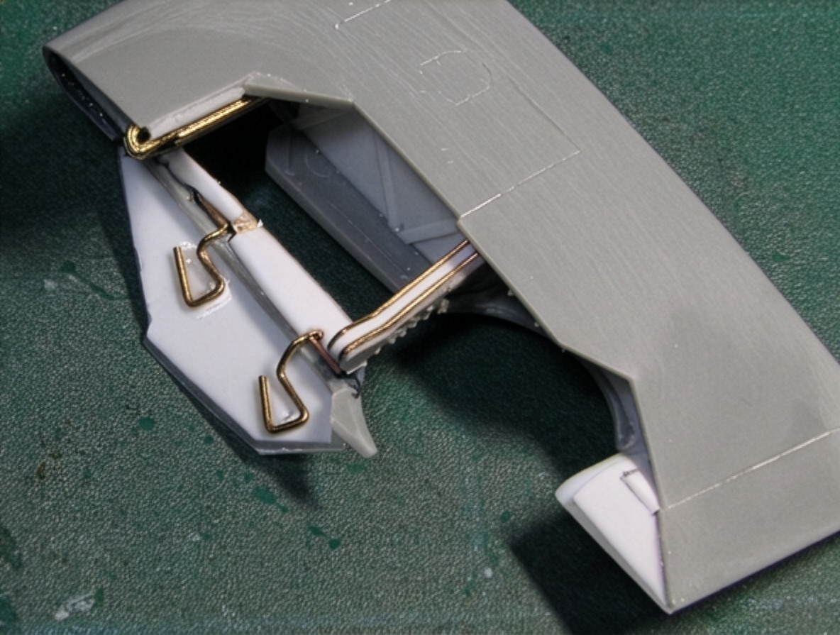
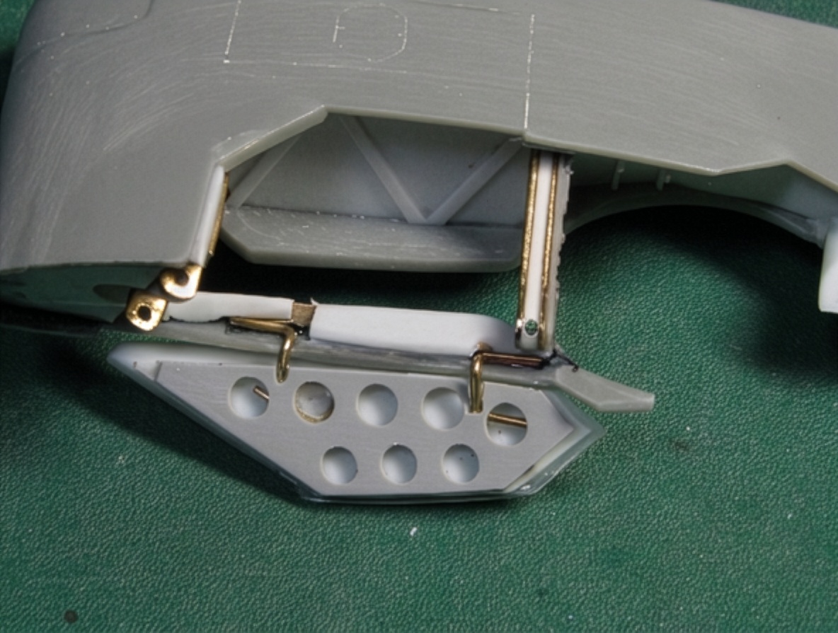
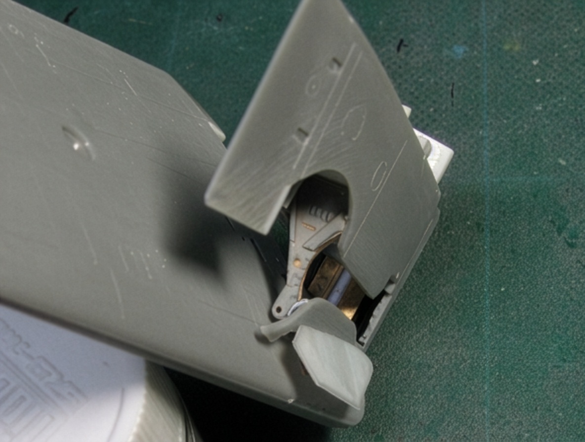
The Small Lower Door
A small door is located on the outer side of the landing-gear compartment.
Its purpose is to prevent the inner and outer wings from interfering with each other during folding.
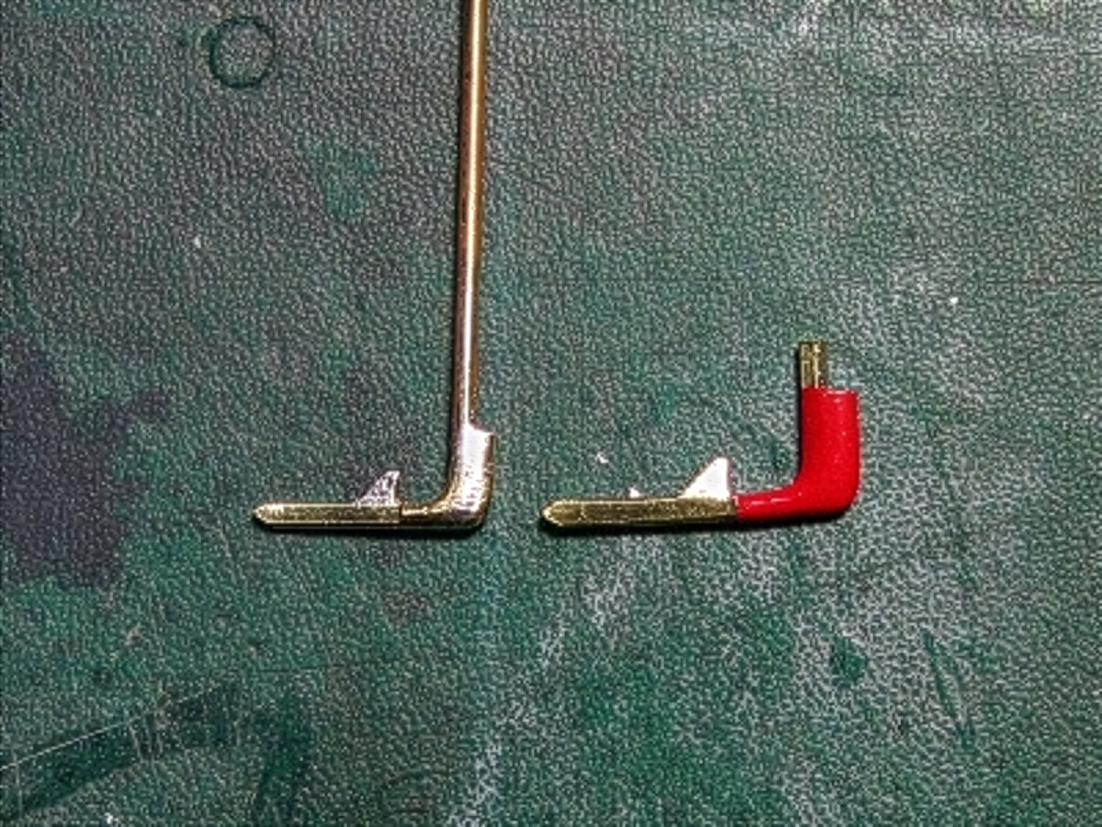
I first produced a rough mechanical sketch.
The orange section represented the door, the gray section the fixed structure, and the hinge consisted of a blue tube and green rod.
The hinge axis can be determined geometrically. When point A moves to A′ and point B moves to B′, the intersection of the perpendicular bisectors of AA′ and BB′ defines the hinge axis.
The actual construction was extremely difficult, much like the wing connecting member.
The hinge axis is located slightly inward from the wing cut line, meaning the green rod must be bent sufficiently to clear the edge.
At the same time, the thickness of the bent rod is severely limited by the available clearance during wing movement.
The inside of the door contains a perforated plate. I cut this from 0.14 mm (0.006 in) plastic sheet using a Craft Robo CC330-20 cutting machine.
The door mechanism was also reproduced in the closed position.
The door can be held in place by friction between the tube and rod, so I deliberately left the mechanism relatively rough rather than making it unnecessarily complicated.
Horizontal Stabilizer
The horizontal stabilizer is one of the areas where the kit is reasonably good.
An intermediate-level modeler could build it essentially out of the box, although it is not completely accurate.
In the kit, the point of maximum airfoil thickness occurs at approximately 30% of the chord.
On the actual aircraft, this point is further aft.
The airfoil is close to a laminar-flow profile and was designed to provide high aerodynamic efficiency at high speed. The same basic airfoil is used on the vertical fin.
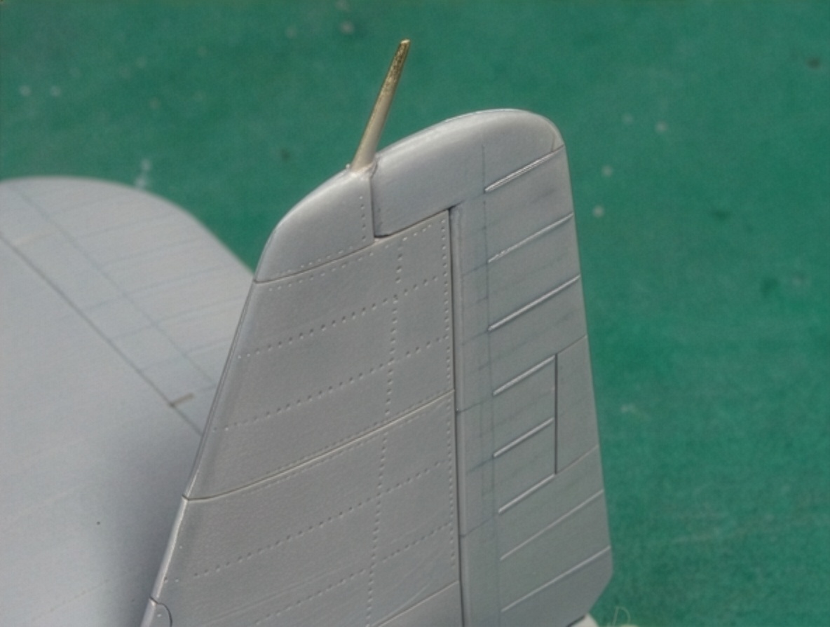
The left and right horizontal stabilizers appear to be interchangeable, but a close examination reveals differences in the upper and lower fuselage connection lines.
Most of the fin structure appears interchangeable, but the panel containing the fuselage connection line differs.
While examining photographs of surviving aircraft, I also noticed a panel line along the leading edge that is absent from some existing drawings.
Some aircraft clearly show the line while others do not.
There are several possible explanations: the line may simply be invisible in some photographs, there may have been two production variations, or it may have been introduced during restoration or repair.
The available evidence was not sufficient to determine the correct answer with certainty.
Fuselage Panel Lines and Rivets
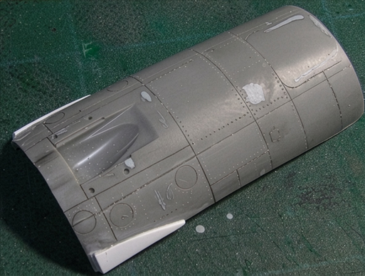
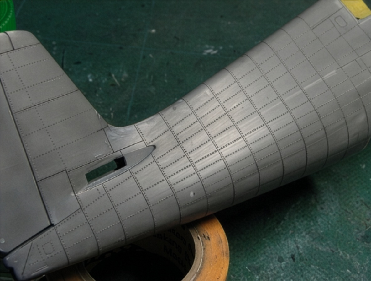
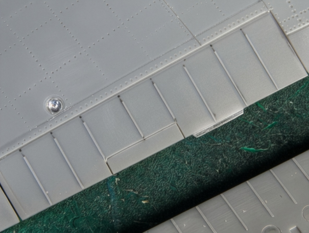
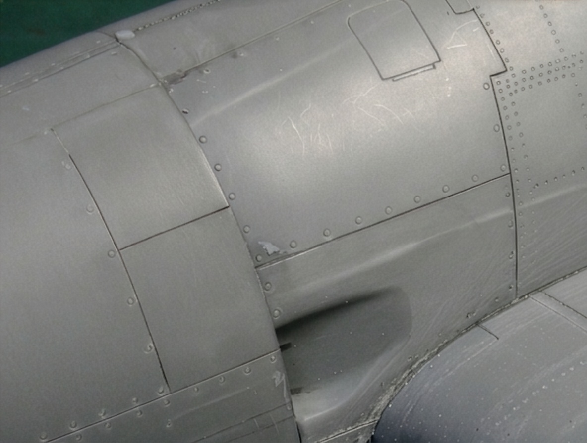
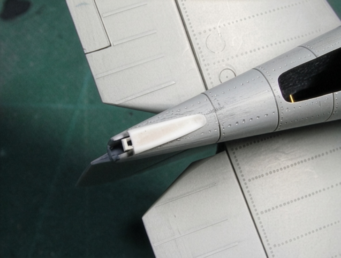
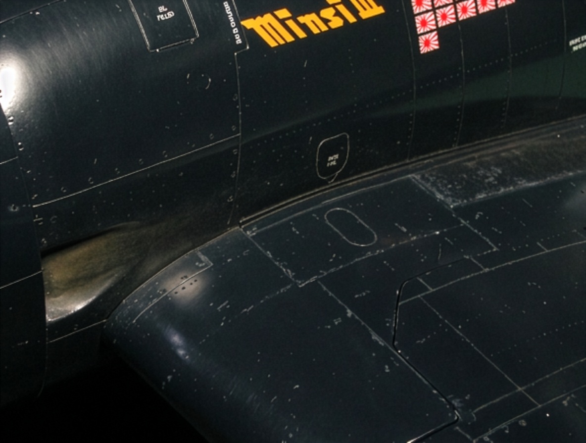
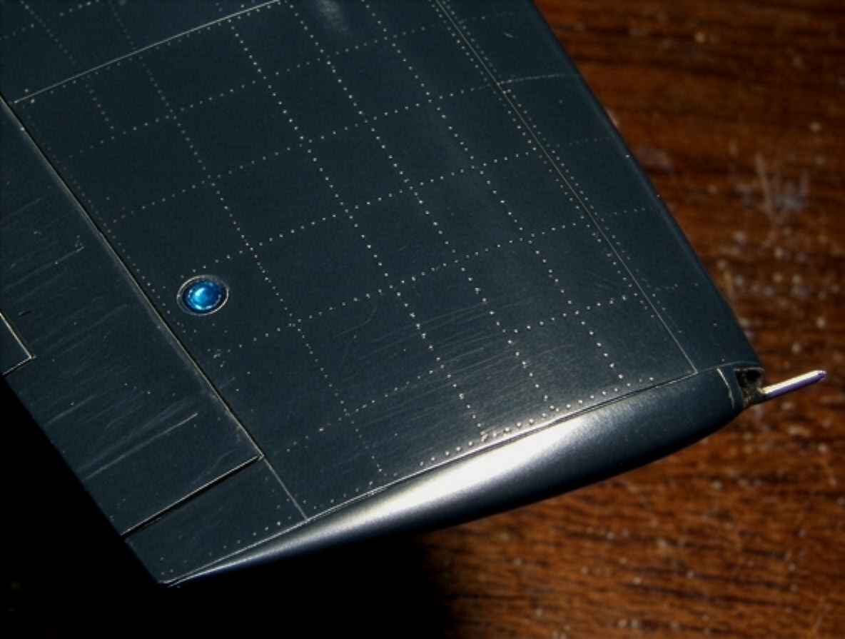
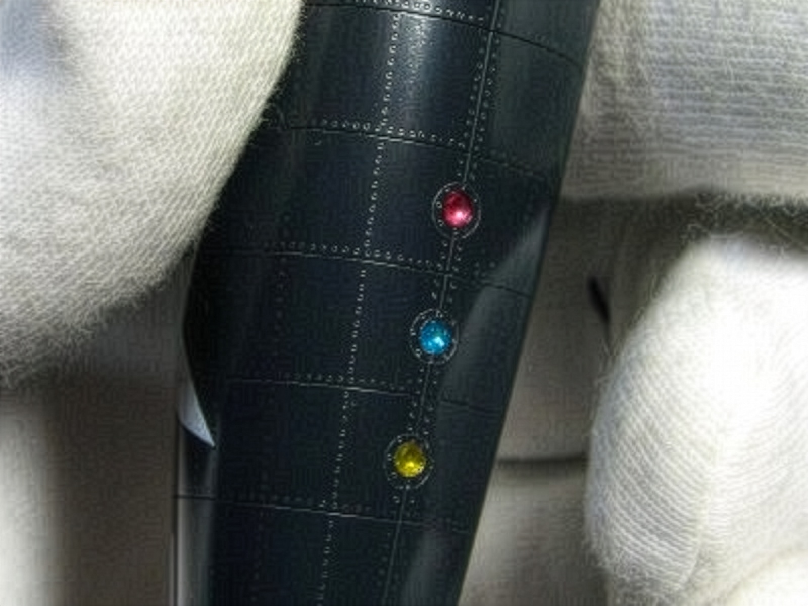
The F6F-5 Hellcat has raised rivets on the rear fuselage, particularly after panel number 3, while the main wing, tail surfaces and forward fuselage use recessed or flat rivet treatment.
I could not reproduce genuinely raised rivets at their exact scale appearance, so different tools were used for the two types.
A No. 1 ball-nose tool, approximately 0.3 mm (0.01 in), was used for the raised rivets.
A No. 0 tool, approximately 0.25 mm, was used for the flat rivets.
Different sizes of tools were used for fasteners according to their location. No. 5 was used for the cowling, while No. 3 and No. 4 were used for smaller access panels.
There may also be minor differences in the stringer arrangement between individual aircraft, particularly on earlier versions such as the F6F-3 Hellcat, but the normal F6F-5 Hellcat arrangement was reproduced here.
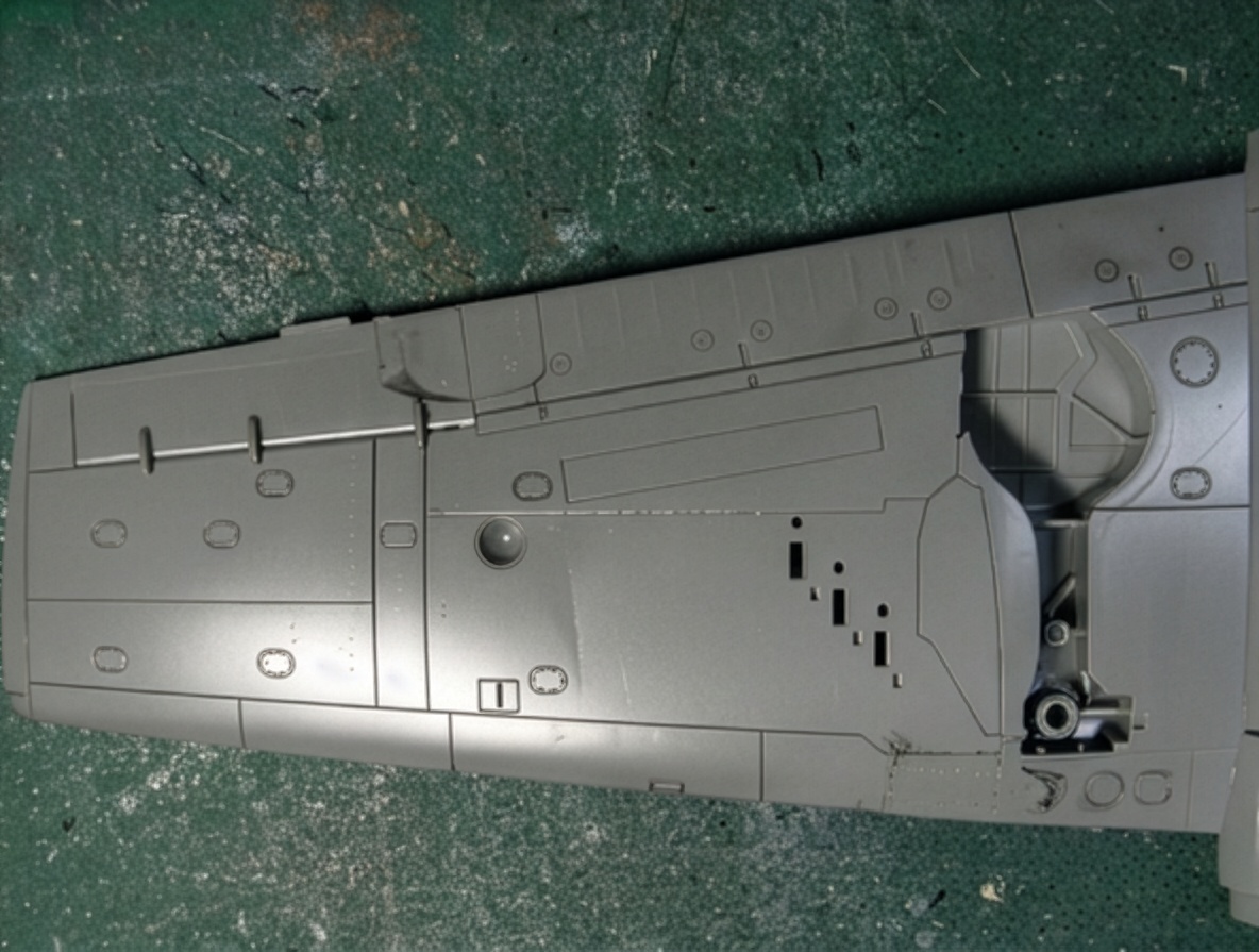
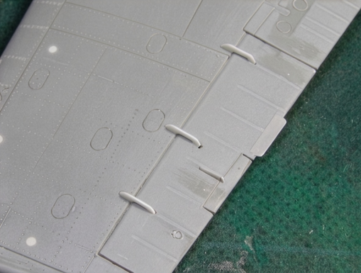
Wing Rivets and Panel Lines
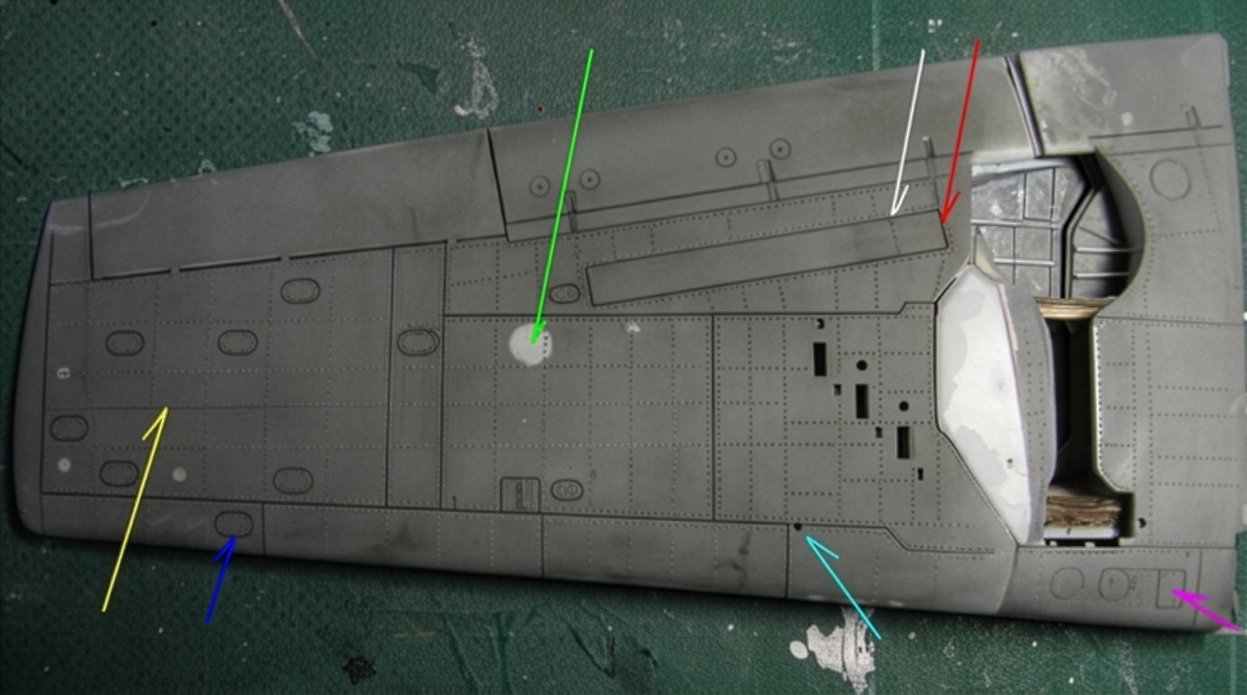
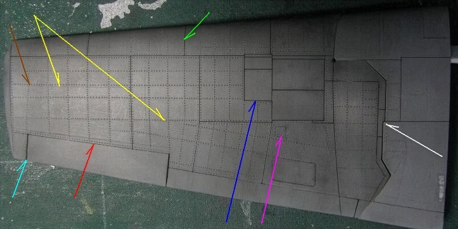
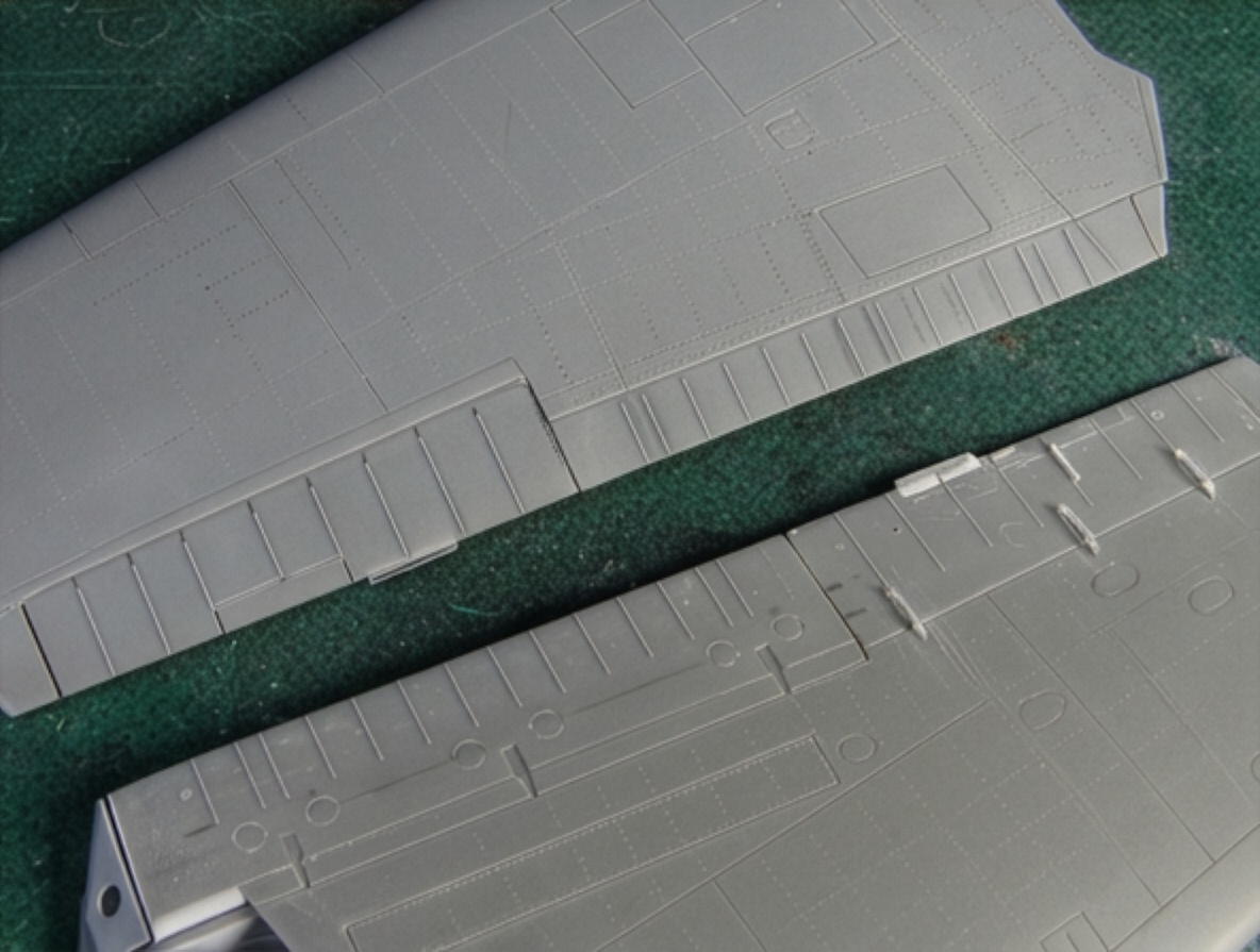
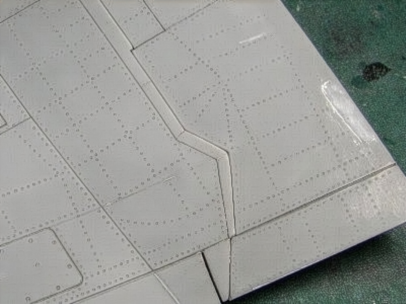
The wing panel layout of the F6F-5 Hellcat differs considerably from that of the F6F-3 Hellcat, particularly on the upper wing surface.
The Hasegawa kit represents the earlier -3 wing arrangement and contains several inaccuracies, so additional work is required to bring it closer to the -5 configuration.
Existing drawings were not considered sufficiently reliable for the final panel-line and rivet arrangement.
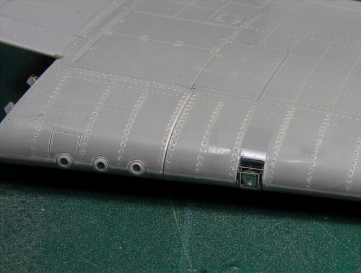
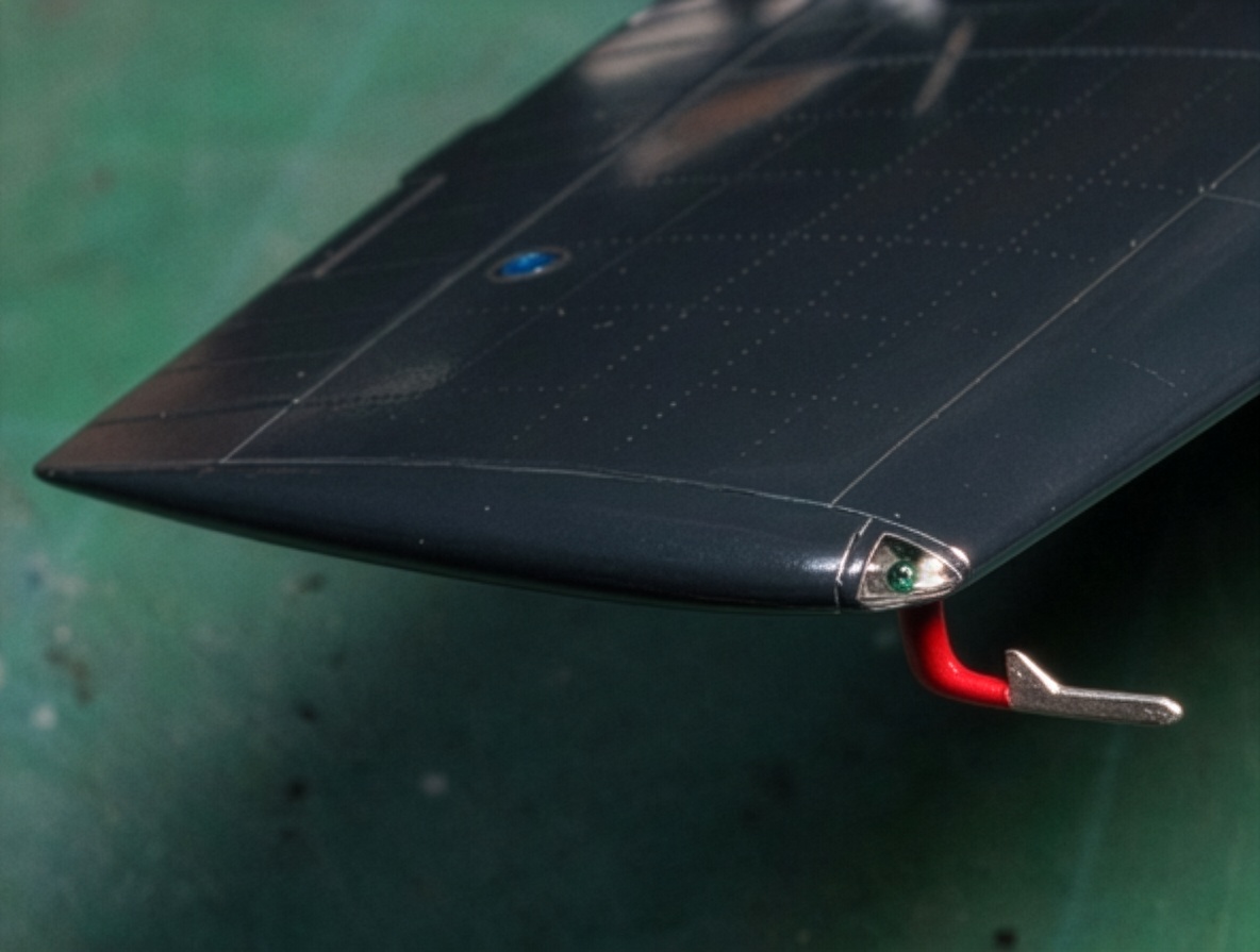
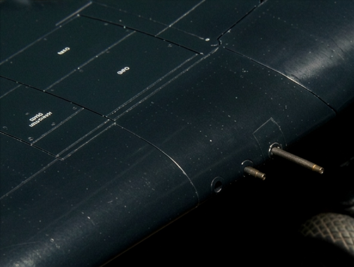
I compared the station numbers, drawings and photographs of actual aircraft and reconstructed the panel and rivet layout as accurately as possible.
Several important observations resulted from this process.
The panel lines generally correspond to surviving restored aircraft, although some lines shown on older drawings were removed when photographic evidence failed to support them.
The panel line on the upper strut flange is exactly 90 degrees to the fuselage centerline.
The corresponding line on the lower flange has a slight sweep because of the taper of the oblique strut.
Some drawings show ribs on the forward main wing bent outward, but I could not confirm this feature photographically.
The inner wing is metal-skinned and therefore also contains rivet detail.
Several small dimensional changes were made to the wing.
The trailing edge of the fixed wing was moved rearward by approximately 1–2 mm (0.04–0.08 in).
The span was increased by approximately 1 mm.
Several panel lines were relocated or removed according to photographic evidence.
The kit access panel was reduced where it interfered with the rivet line.
The actual wing-folding parting line is straight and does not contain the crank shown in the kit.
The large access panel beneath the box ahead of the wing was enlarged by approximately 5 mm (0.2 in) toward the fuselage.
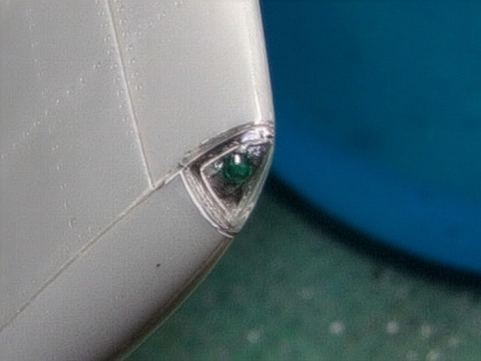
The port landing-light opening was filled because this type of light is associated with the F6F-3 Hellcat, not the F6F-5 Hellcat.
Additional access panels were added and their positions adjusted according to the available evidence.
The two wings are essentially identical unless specifically noted otherwise.
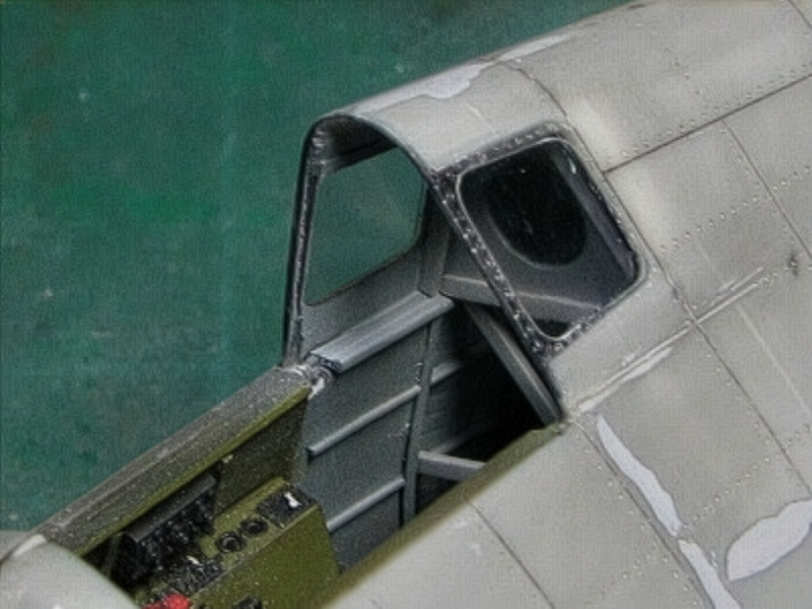
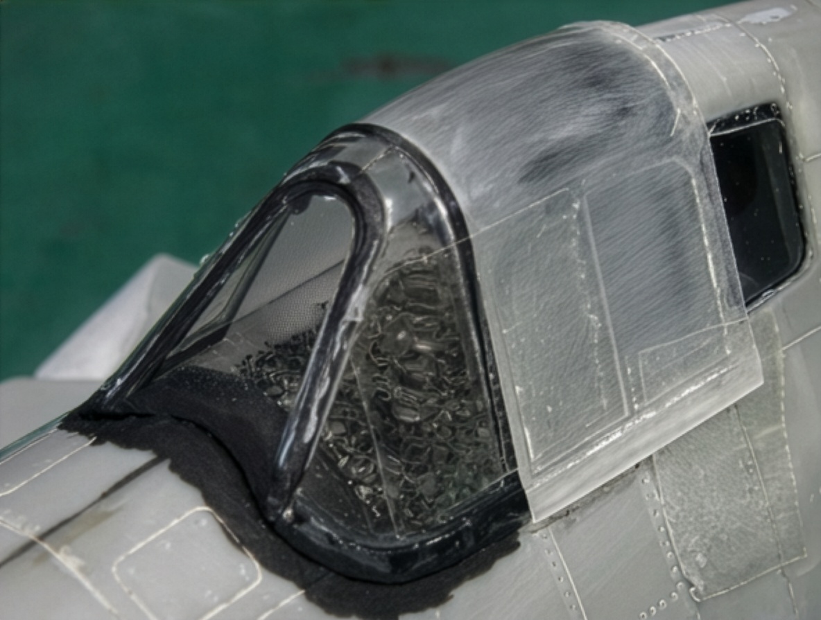
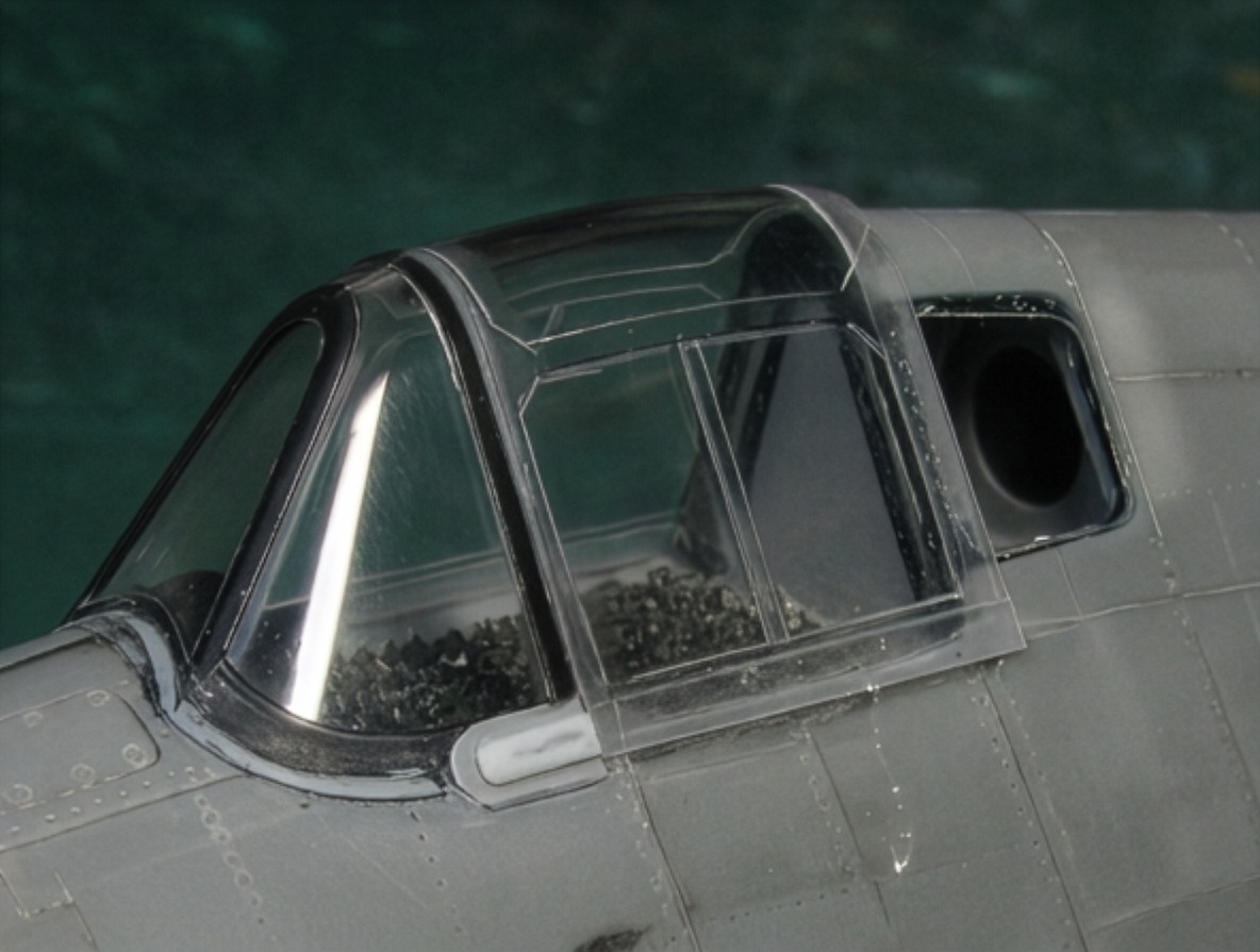
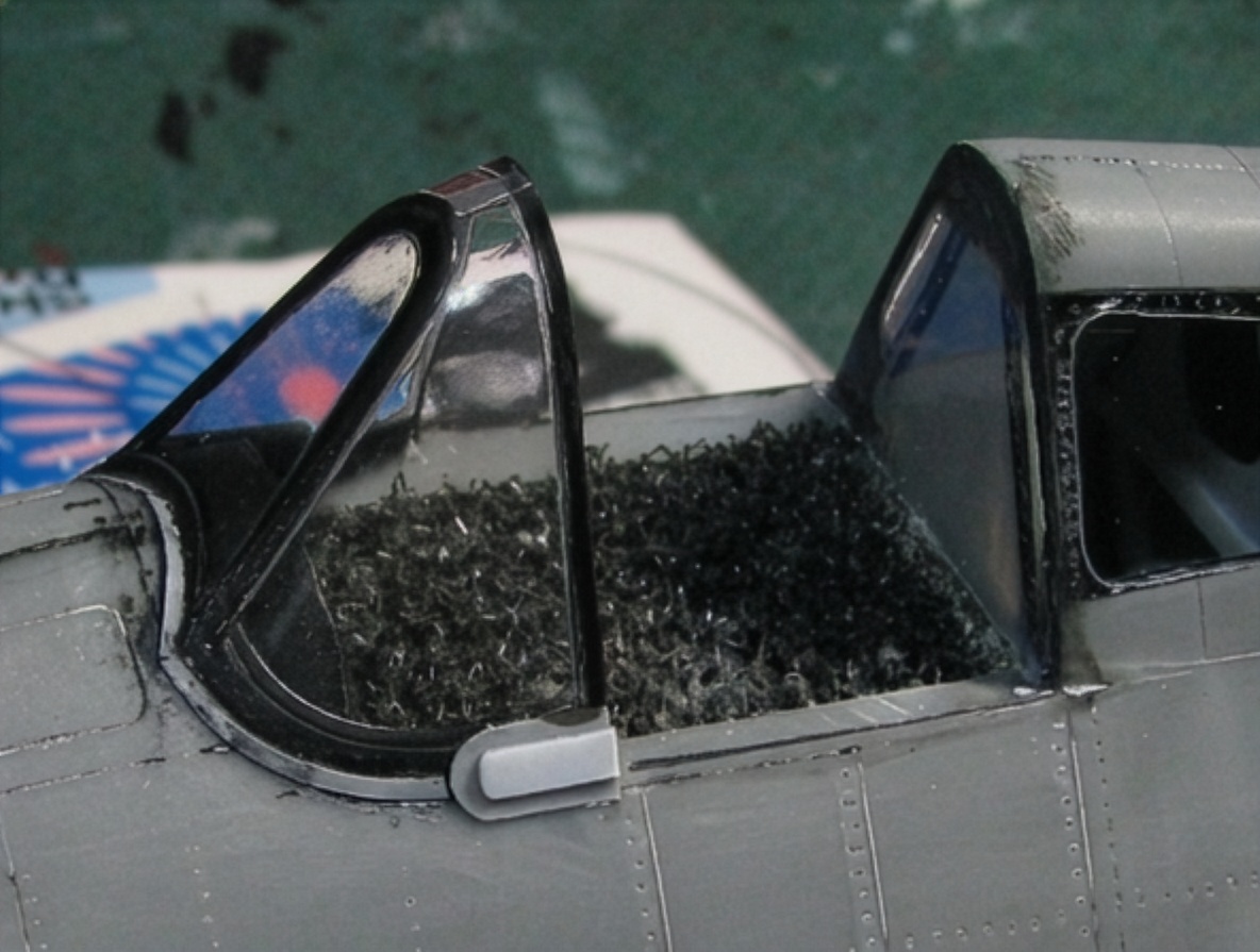
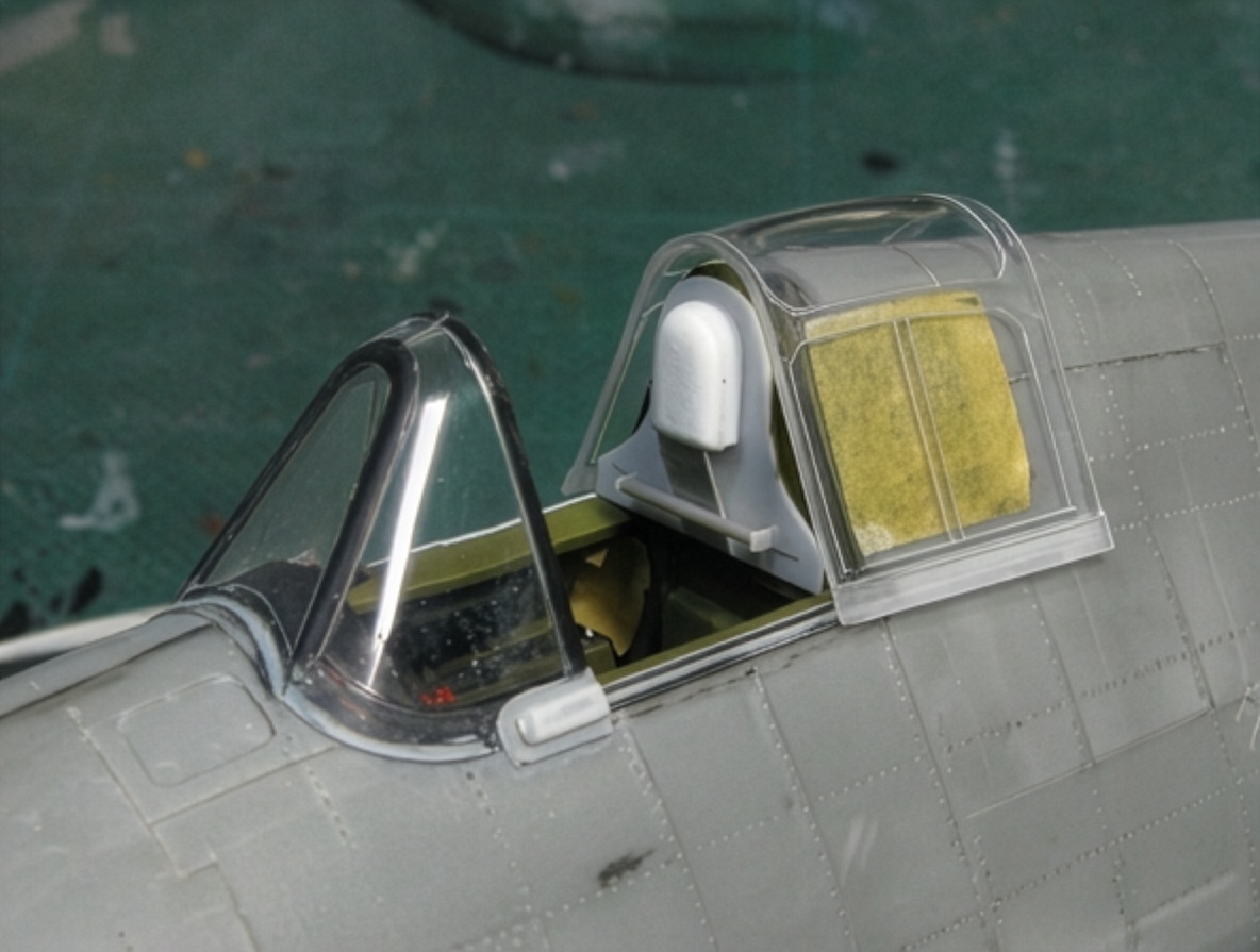
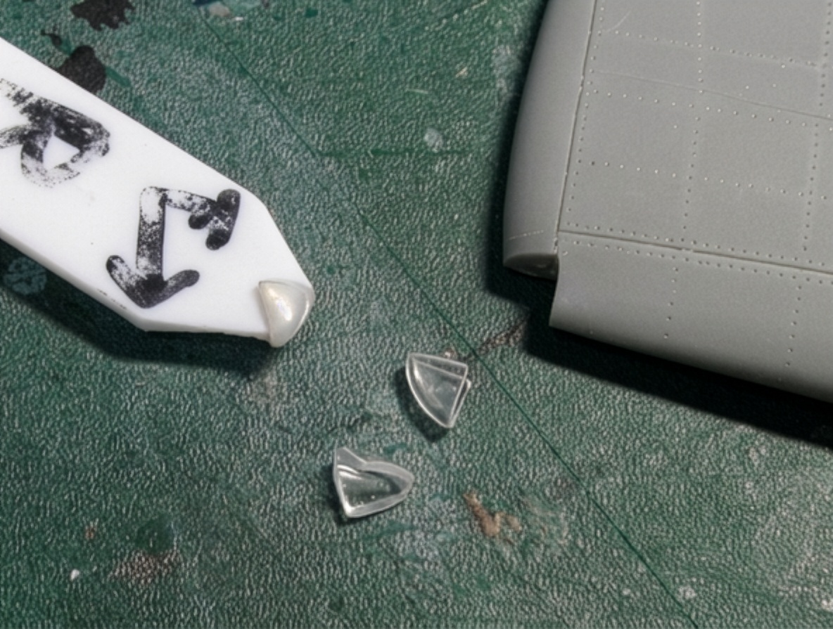
Windshield and Sliding Canopy
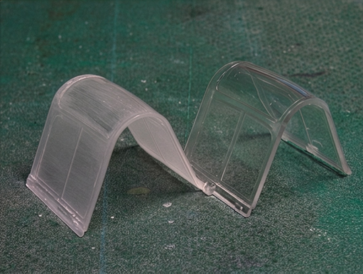
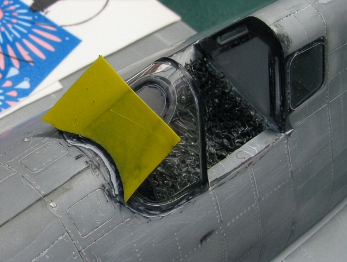
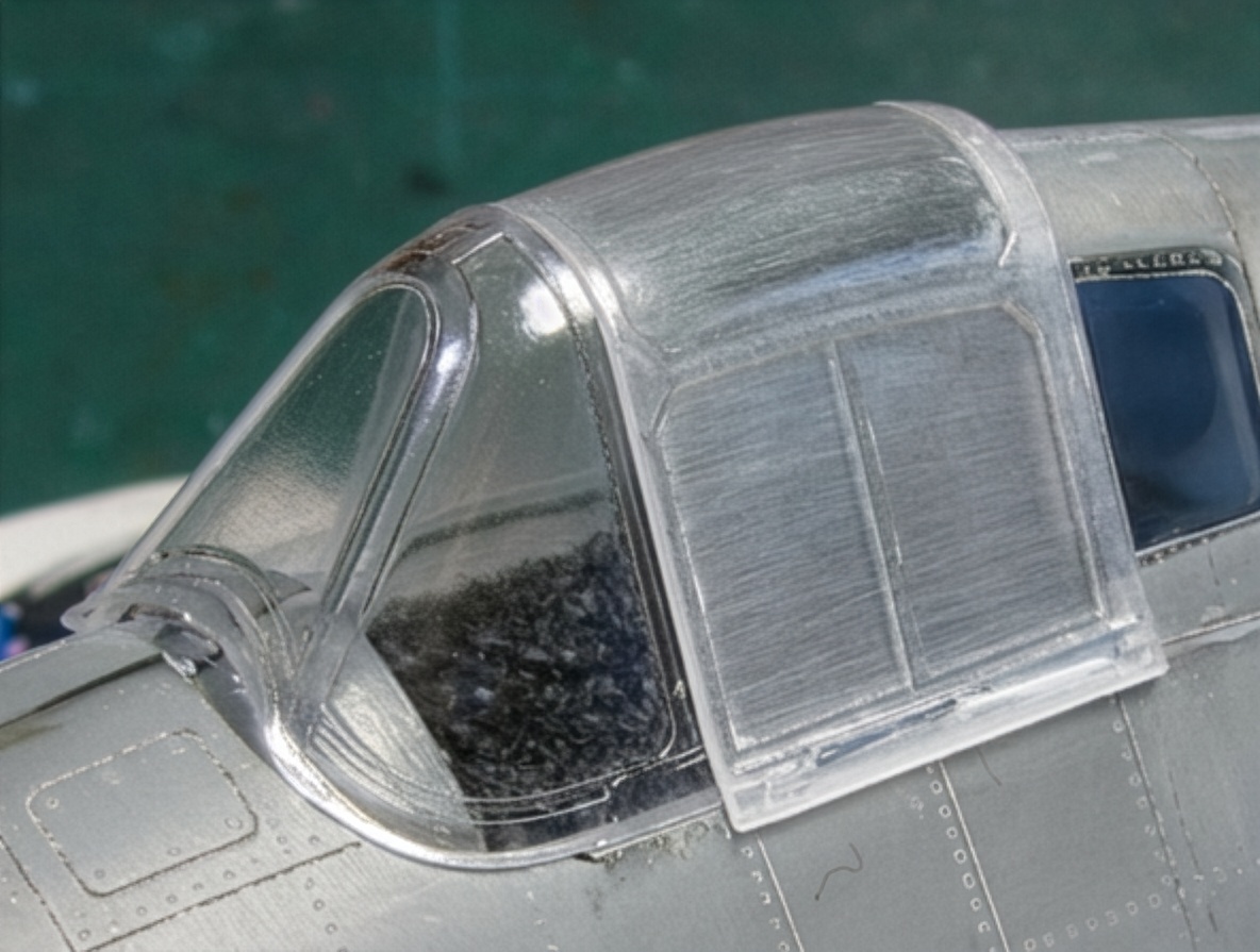
The Eduard windshield and canopy were used because their basic shapes are very good.
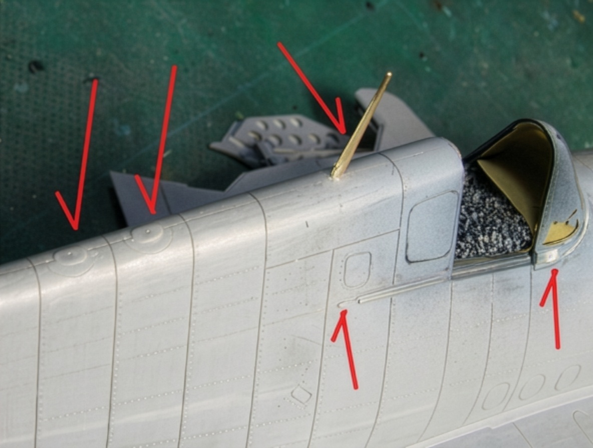
I wanted the canopy to remain capable of sliding open and closed.
To make this possible, the rear edge of the canopy section had to be sanded extremely thin so that it could move correctly along the fuselage.
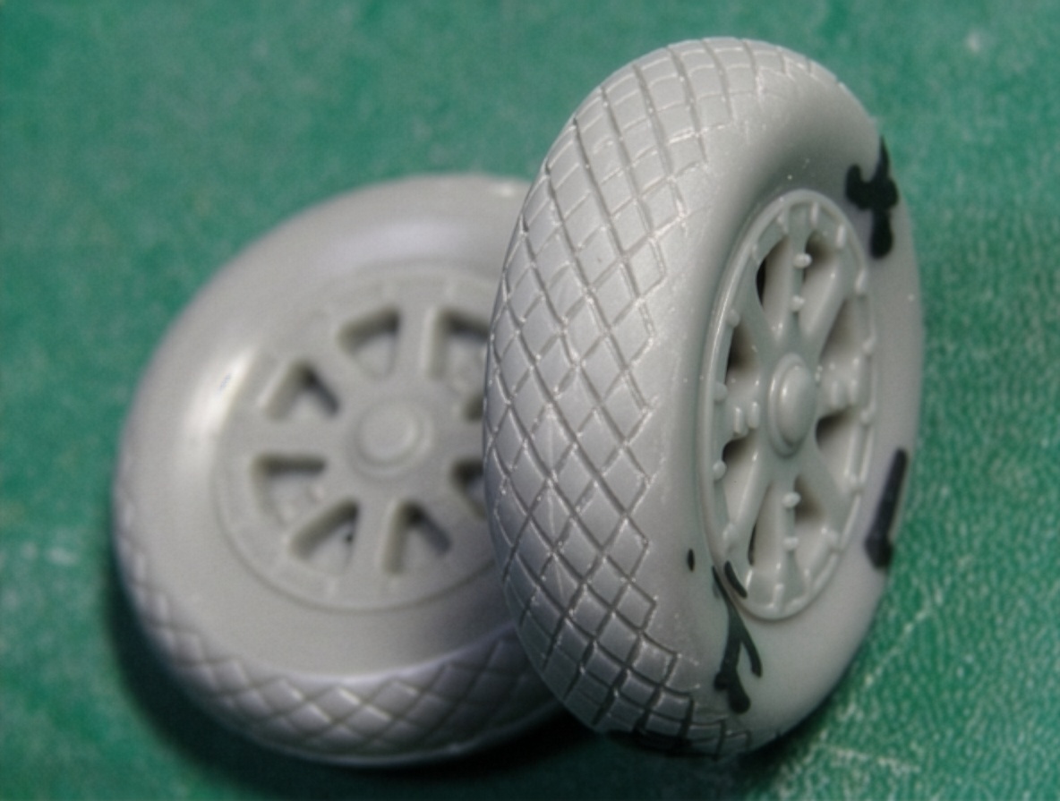
Correcting the Tires
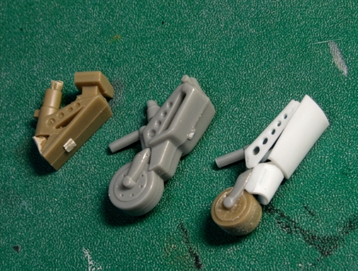
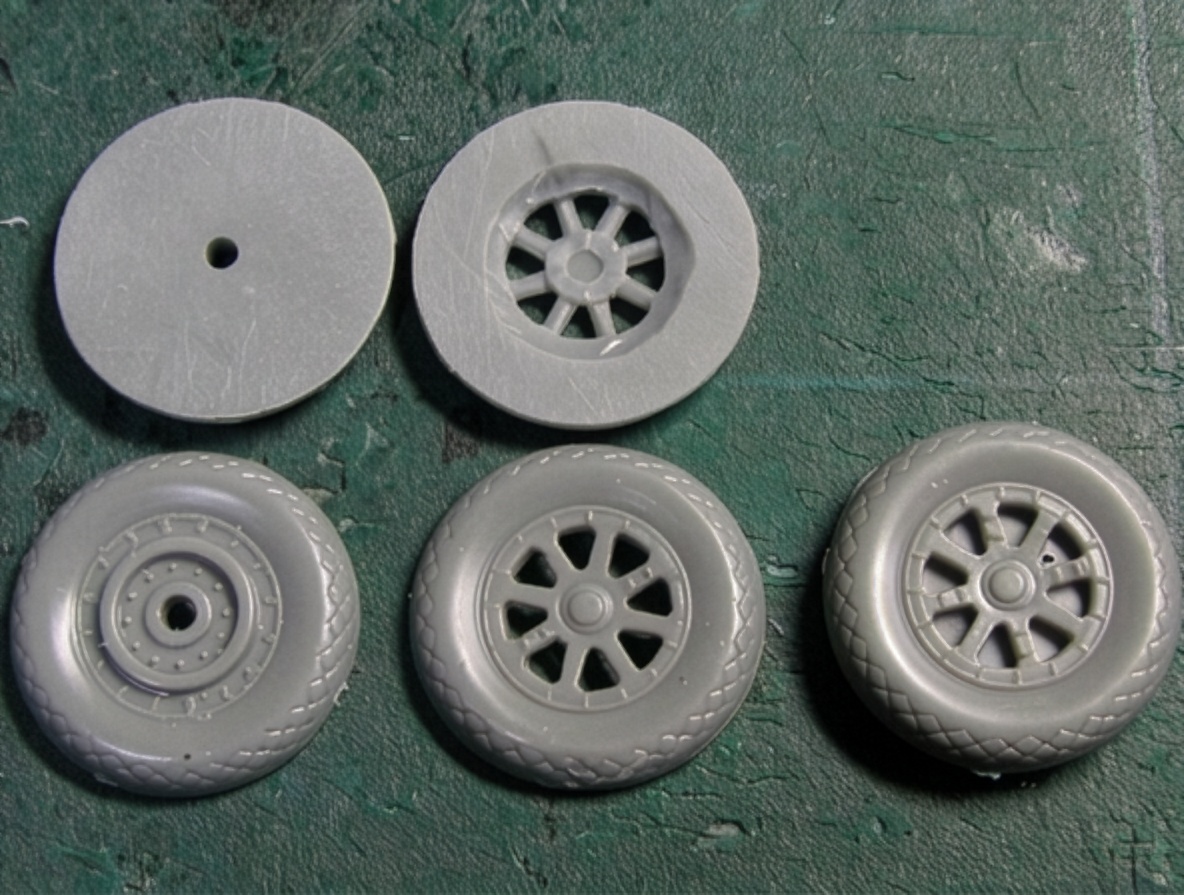
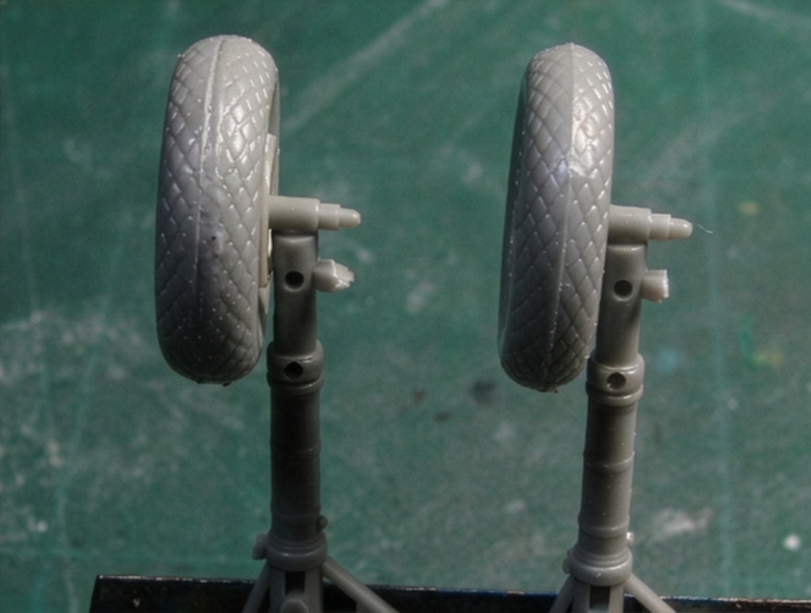
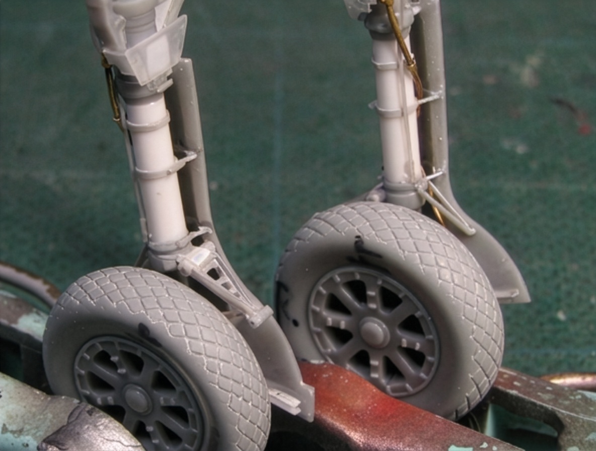
The thin Hasegawa tires weaken the heavy appearance of the F6F-5 Hellcat.
To restore the correct visual weight, the tire width was increased by combining two sets of wheels.
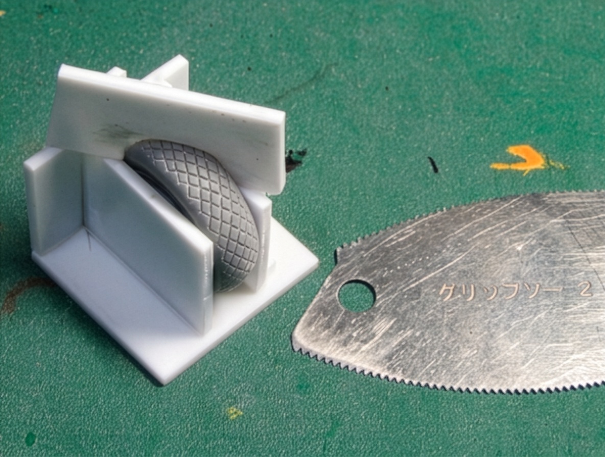
The diamond tread pattern was then reproduced using a thick carving saw and a small jigsaw.
The wider tires make an immediate difference to the stance of the finished model.
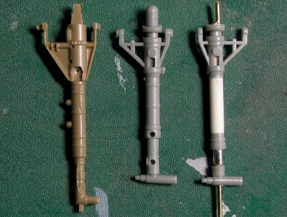
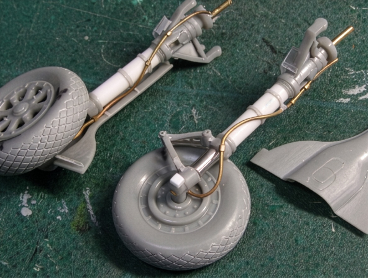
Main Landing Gear
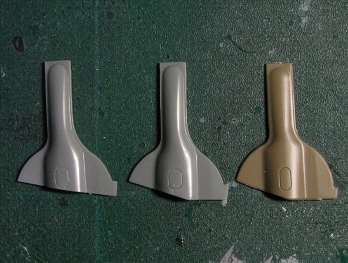
The landing-gear doors of the F6F Hellcat changed during production.
The kit part can be used for the early F6F-3 Hellcat configuration.
The later arrangement was introduced during production and remained in use through the final Hellcat versions.
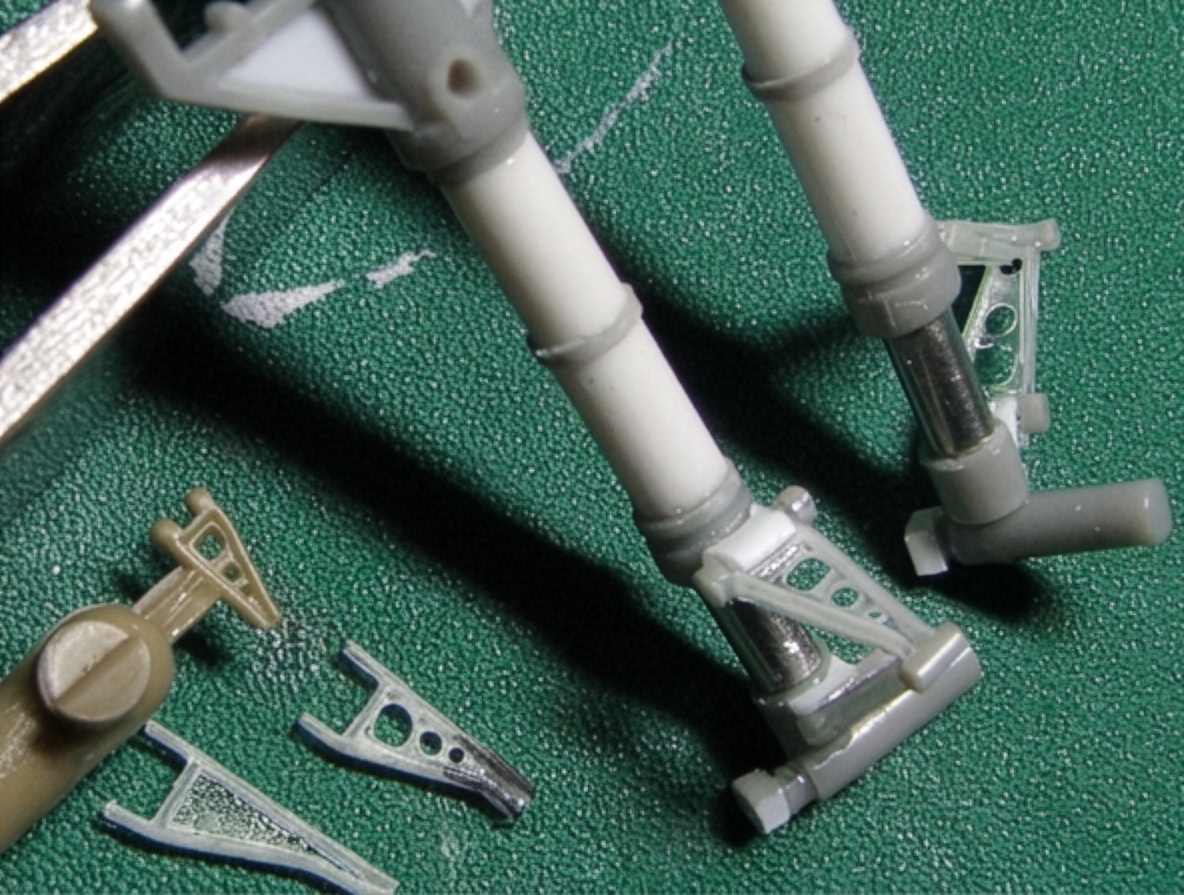
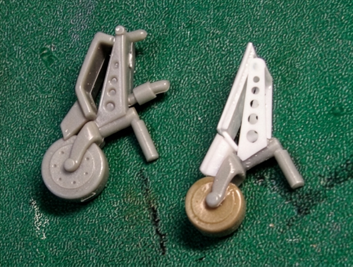
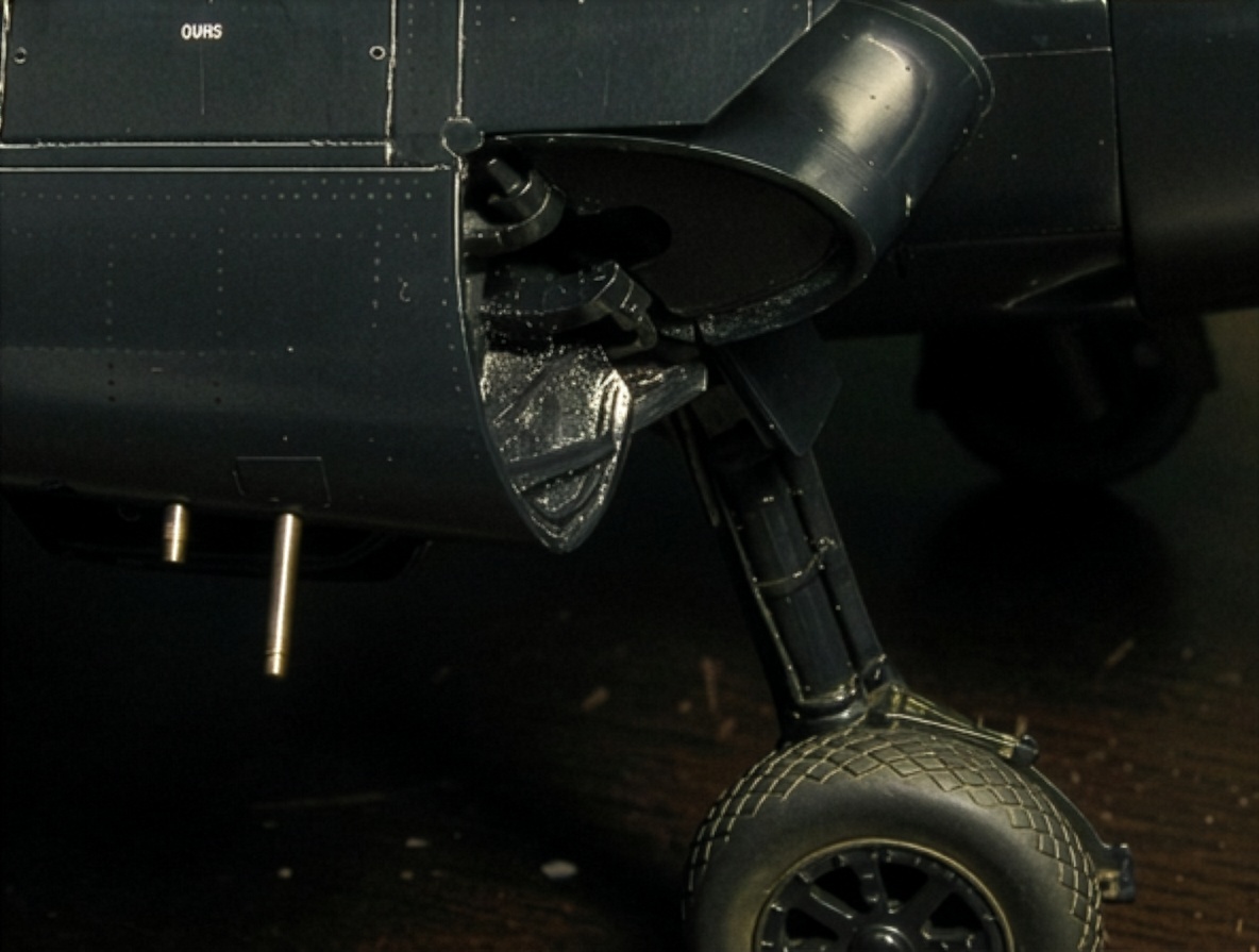
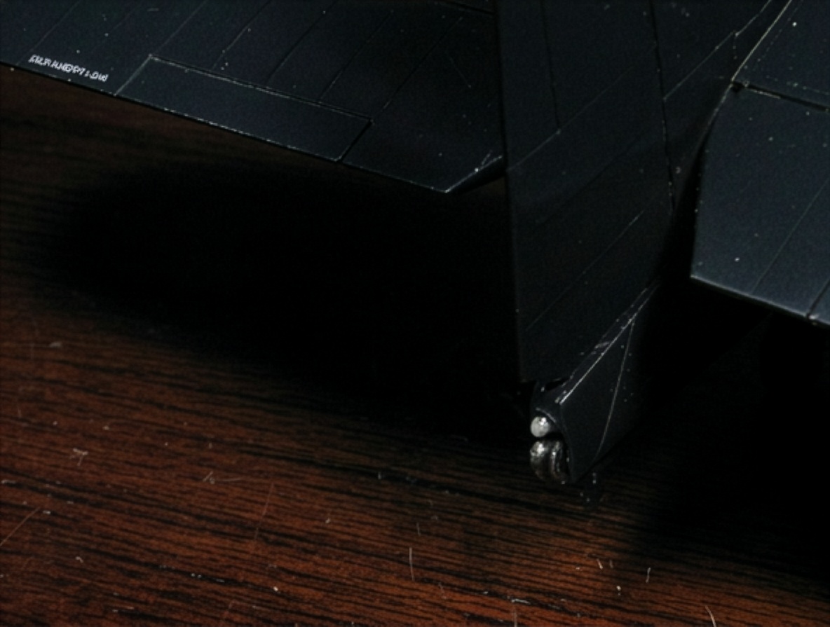
The Hasegawa landing-gear door itself is well molded, but its position relative to the landing-gear leg is incorrect. The door sits too low.
The Eduard part also has an incorrect shape.
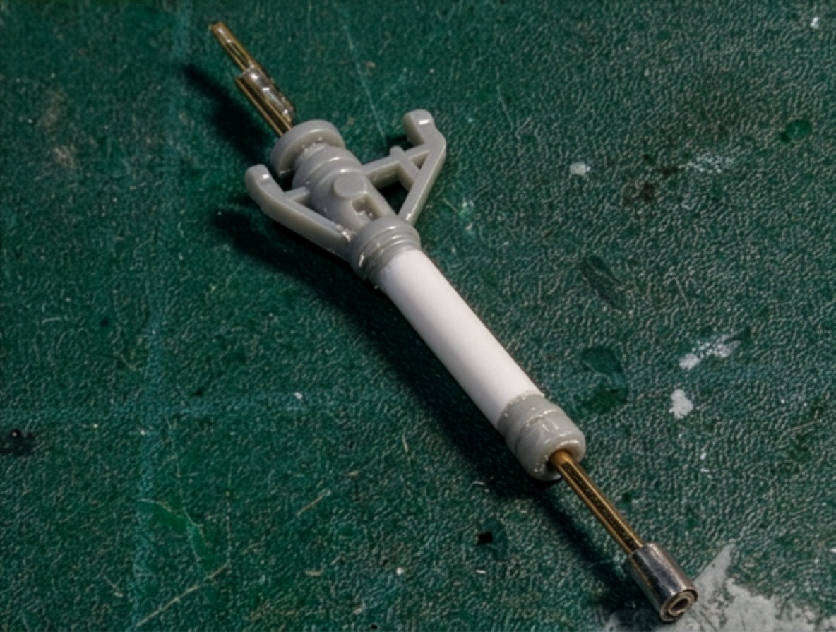
The torque link is another important feature when modeling the Hellcat because it is highly visible.
Engraved aftermarket parts are convenient but lack convincing three-dimensional depth.
For that reason, I scratch-built the torque links from 0.2 mm (0.008 in) styrene sheet, reproducing their characteristic H-shaped cross-section.
Correcting the Propeller
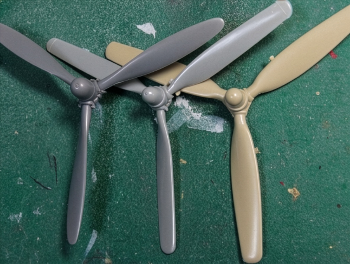
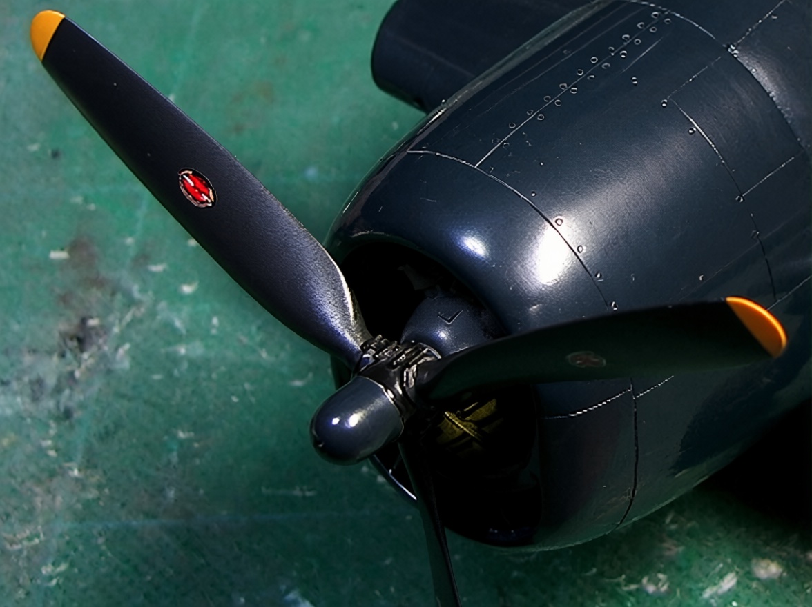
The kit propeller is not bad, but the spinner is too small and the blades are slightly too narrow.
This is a characteristic weakness of the Hasegawa representation.
The easiest solution would have been to use a Tamiya F4U-1D Corsair propeller, but I did not have one available.
Instead, I combined parts from my spare-parts collection.
The center section came from an Accurate Miniatures SB2C-1 Helldiver, while the Hamilton Standard paddle blades came from a Tamiya P-47D Thunderbolt.
The Tamiya blades have a very convincing shape, so they only required sanding to reduce their thickness.
The corrected propeller, with its increased width and revised shape, gives the model a much stronger visual impression of the high power and performance associated with the F6F-5 Hellcat.
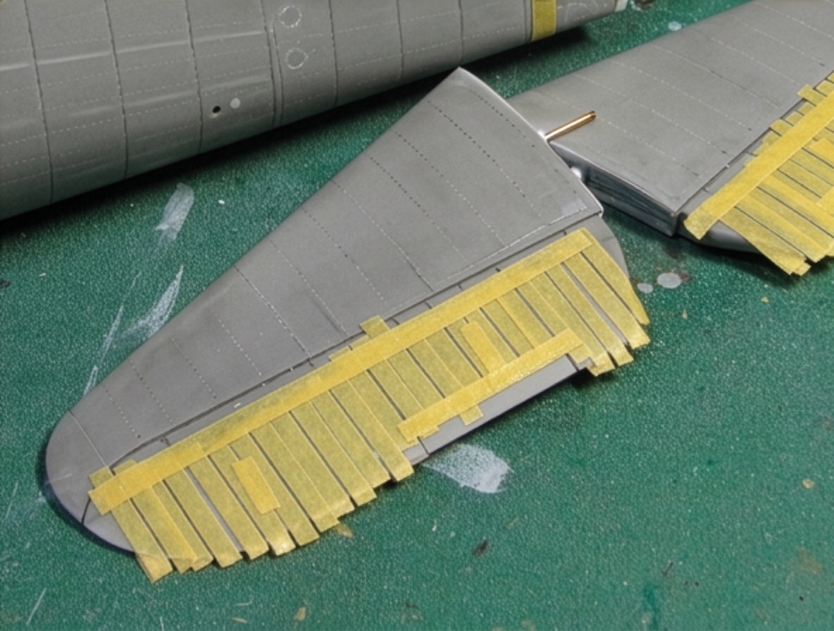
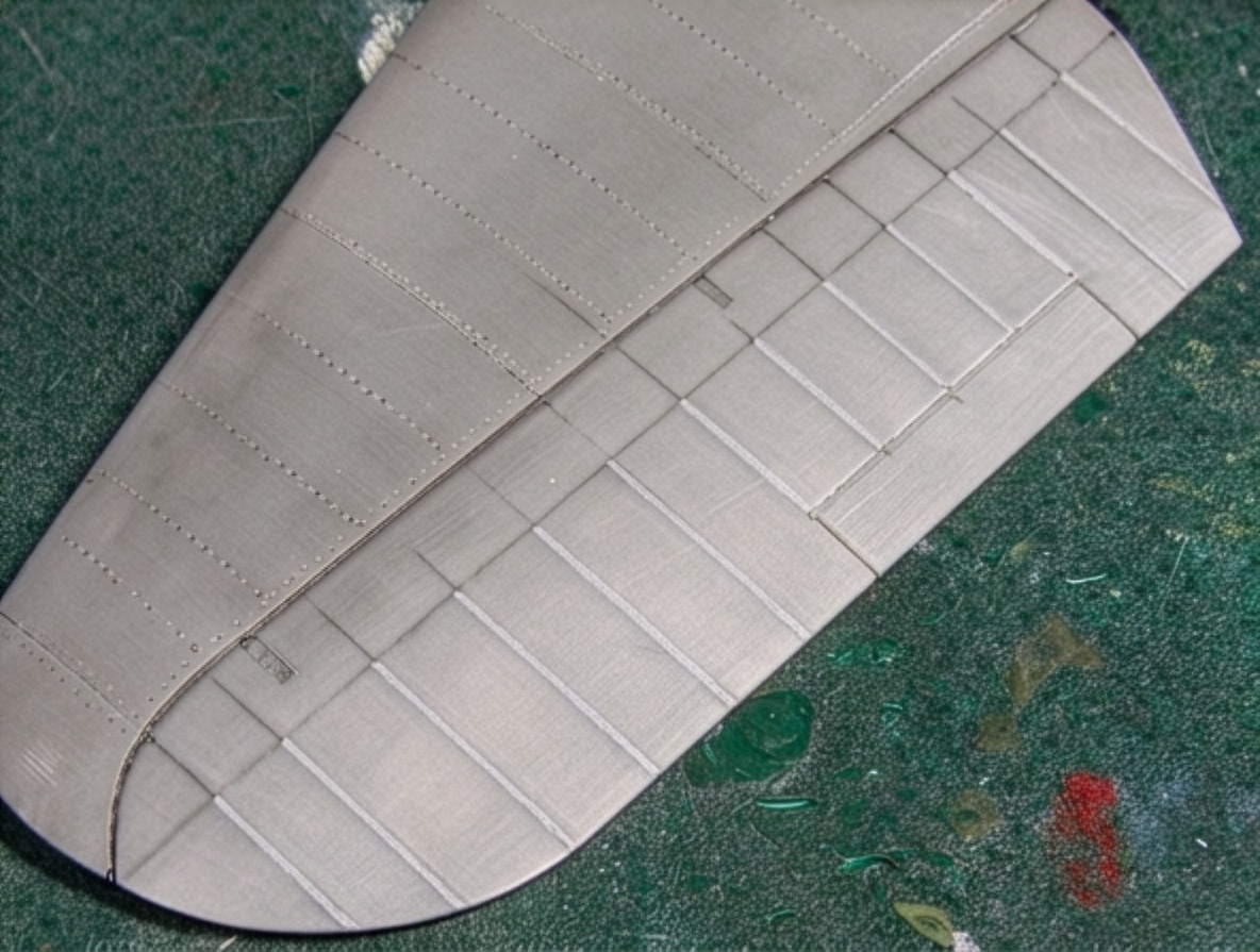
Control Surface Details
The control surfaces were reproduced with their characteristic surface arrangement.
The fixed-blade structure was reproduced using aluminum foil.
Surface Preparation and Painting
After completing the structural and surface corrections, sufficient primer and surface material were applied to prepare the model for painting.
The surface was kept under close inspection throughout the process because the extensive fuselage stretching, bending and sanding could easily introduce imperfections.
The objective was not simply a clean model, but a clean surface that preserved the corrected geometry.
Historical Research – F6F-5 Hellcat “Minsi III”
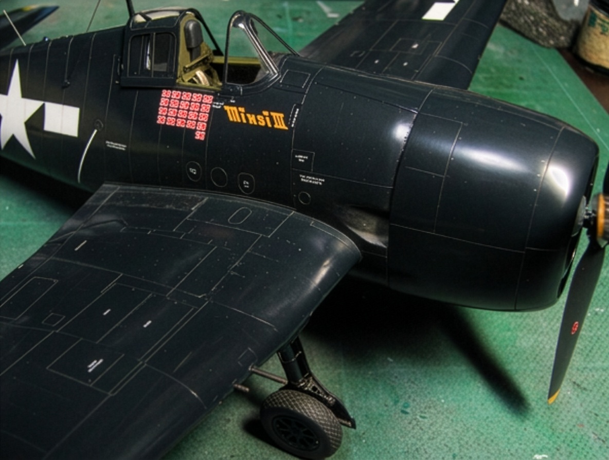
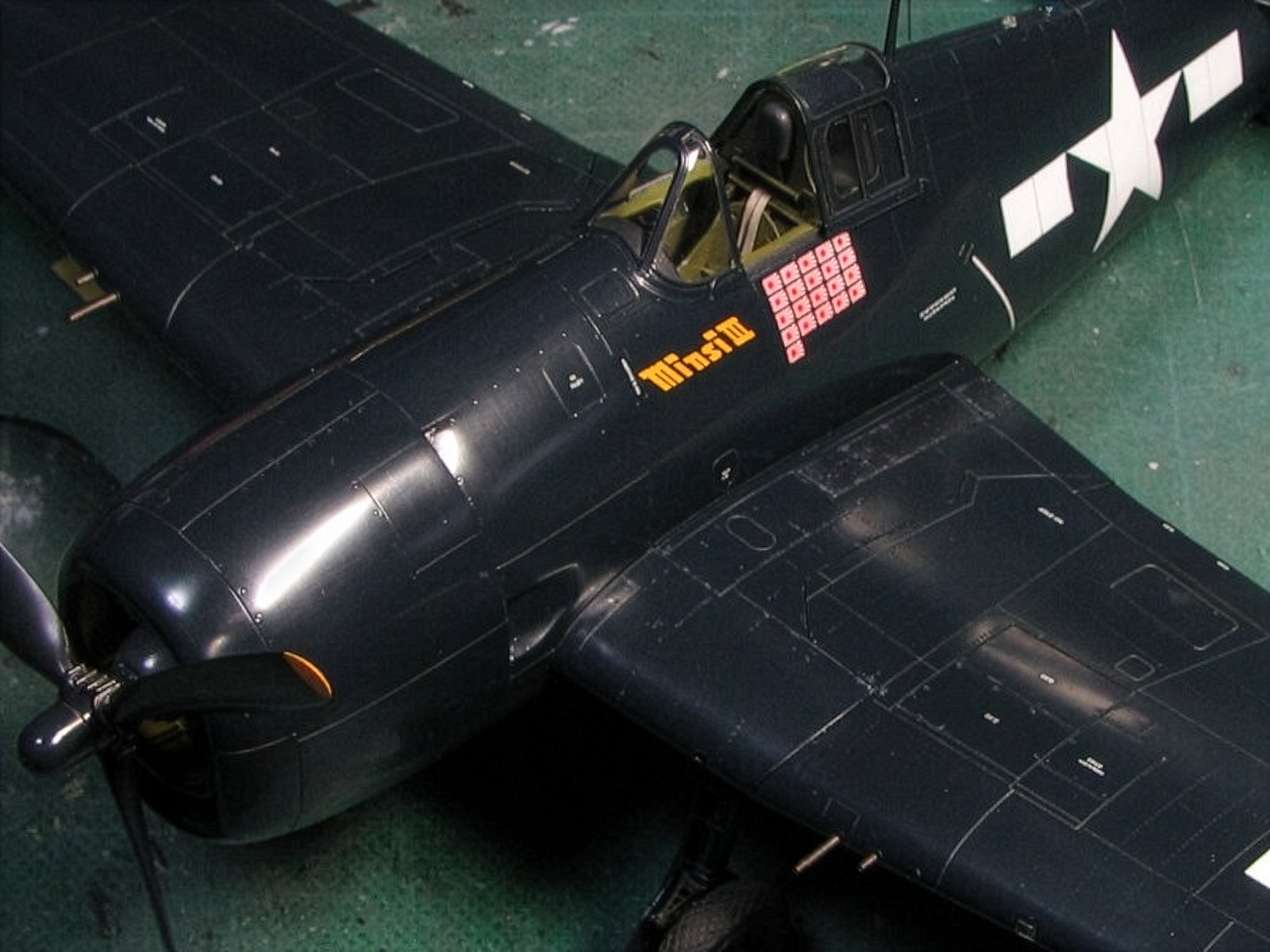
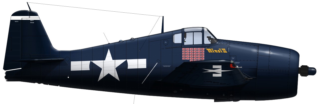
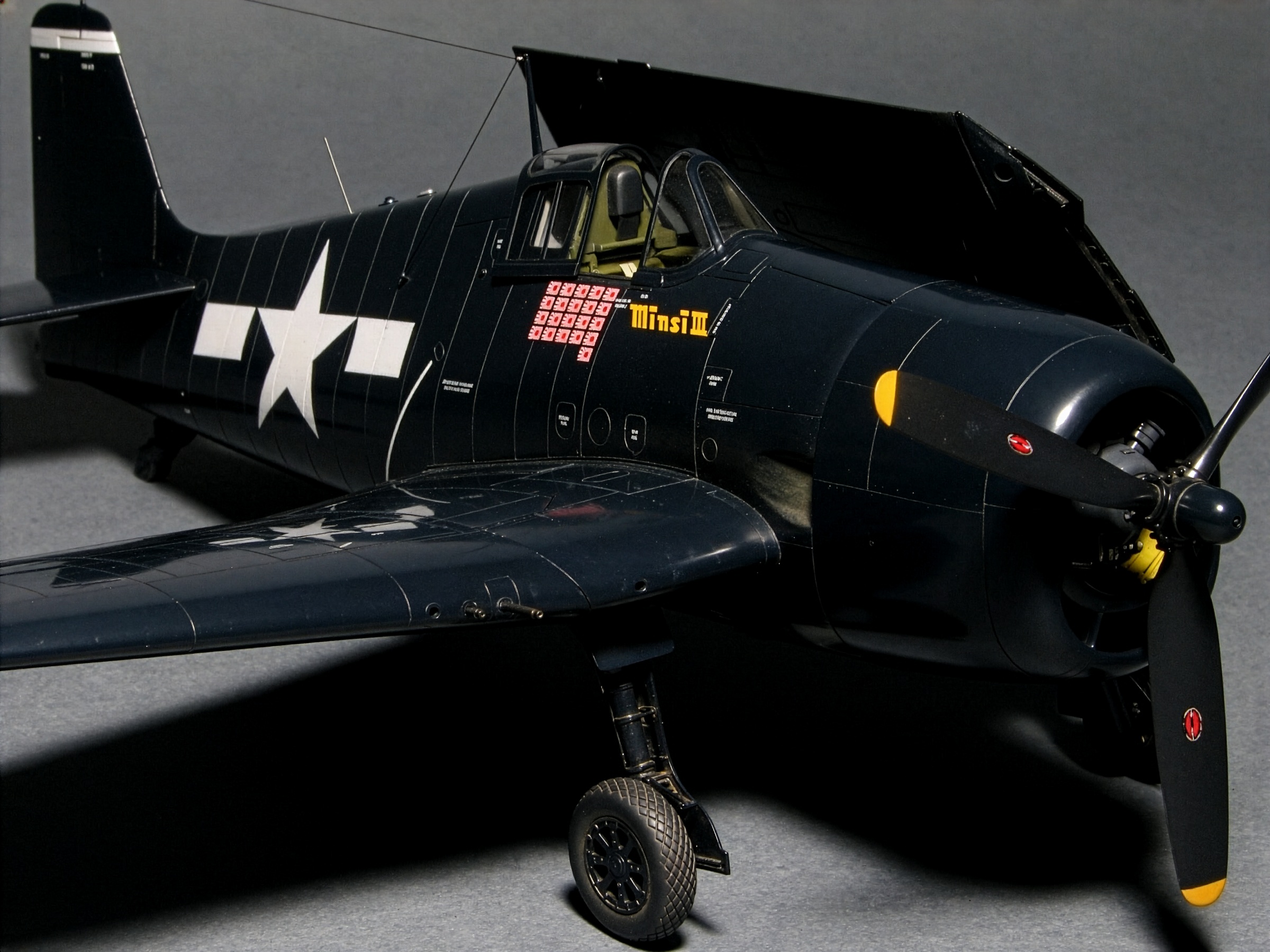
For the final markings, I selected F6F-5 Hellcat “Minsi III” BuNo 70143, flown by Commander David McCampbell, the U.S. Navy’s top ace and commander of Carrier Air Group 15 aboard USS Essex.
This aircraft is an especially interesting subject because several commercially available decal sheets and marking guides contain incorrect details.
Photographs of the actual aircraft provide the most useful evidence, although the available photographs show the starboard side.
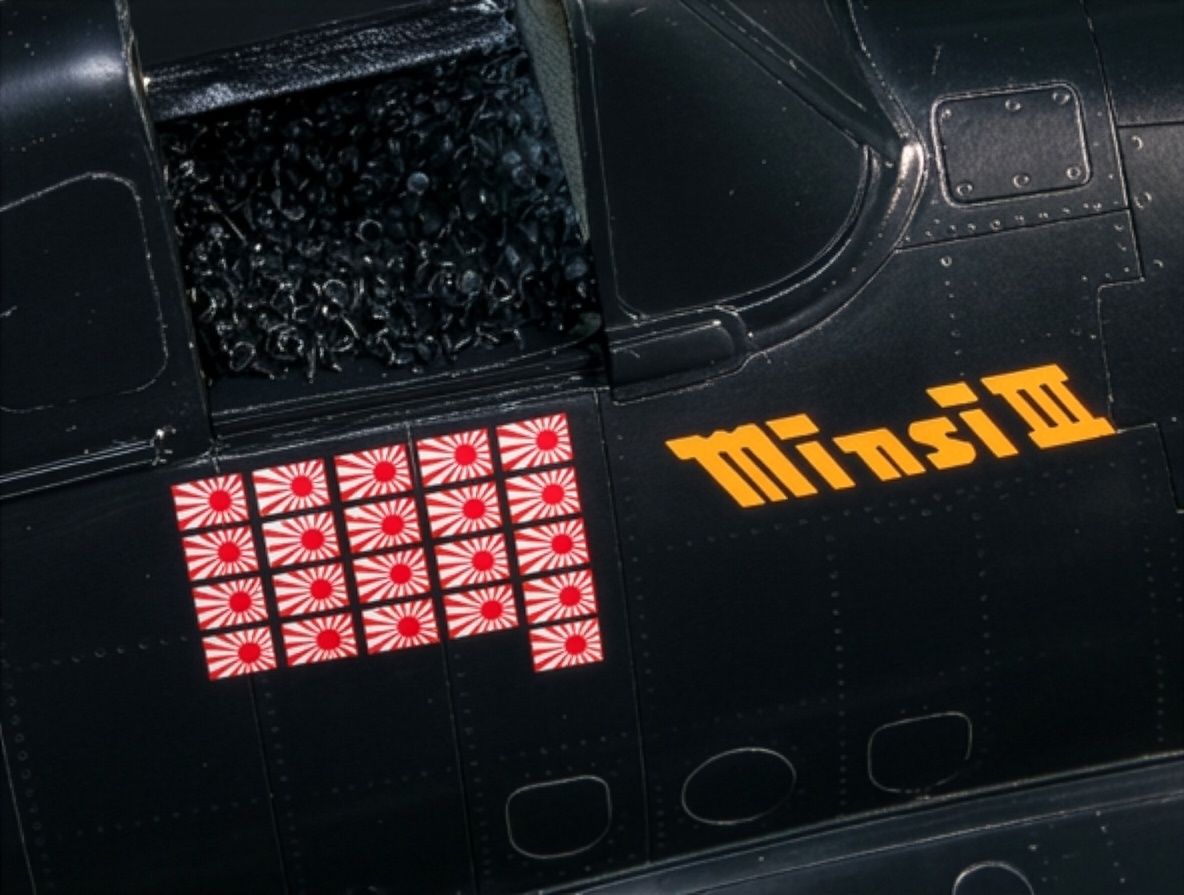
The “Minsi III” lettering, its size, position and color, together with the victory-score markings, were reconstructed from photographic references.
The lettering was essentially traced from the actual photograph.
The original shape of the Roman numeral “III” was not particularly attractive, so I made a small design correction when reproducing it on the model.
The number and arrangement of the victory markings were confirmed from the photographs as 19, 21, 30 and 34, representing different documented conditions of the aircraft.
Tail Markings
A 5-inch-wide white stripe is present on the upper section of the vertical tail.
The earlier Minsi II carried the small “CAG” lettering inside this white band.
For Minsi III, however, the available photograph is not clear enough to confirm the presence of the lettering.
I therefore did not consider it proven that the “CAG” marking was present.
The Aeromaster decal sheet includes “CAG” lettering on the small square landing-gear cover, but there is no photographic evidence available to confirm it.
My impression is that the decal manufacturer may have assumed the marking existed because it was visible on Minsi II.
Colors and Insignia
The sea-blue color of the wheels is confirmed photographically.
The spinner and propeller hub were dark.
I painted the spinner Gloss Sea Blue, although this particular detail could not be conclusively confirmed from the available photographs.
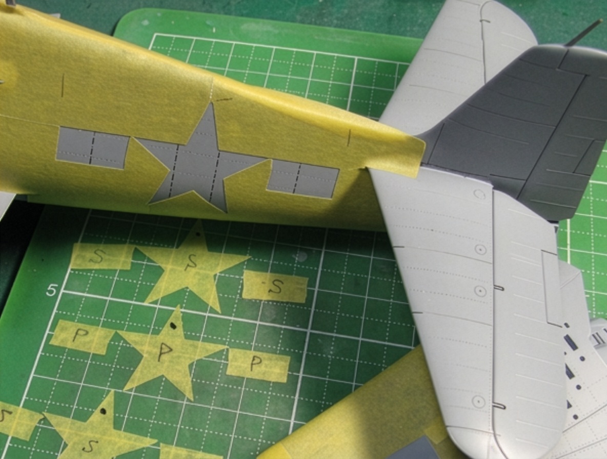
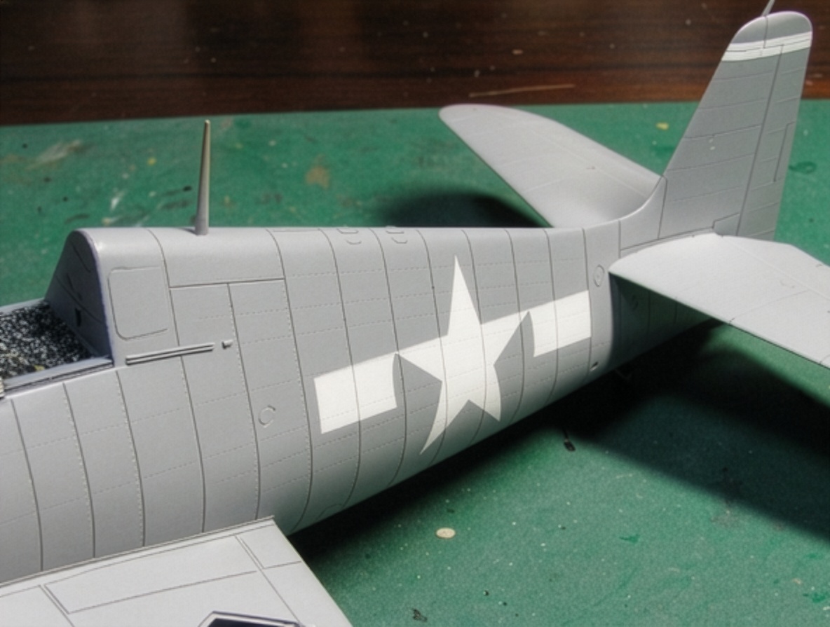
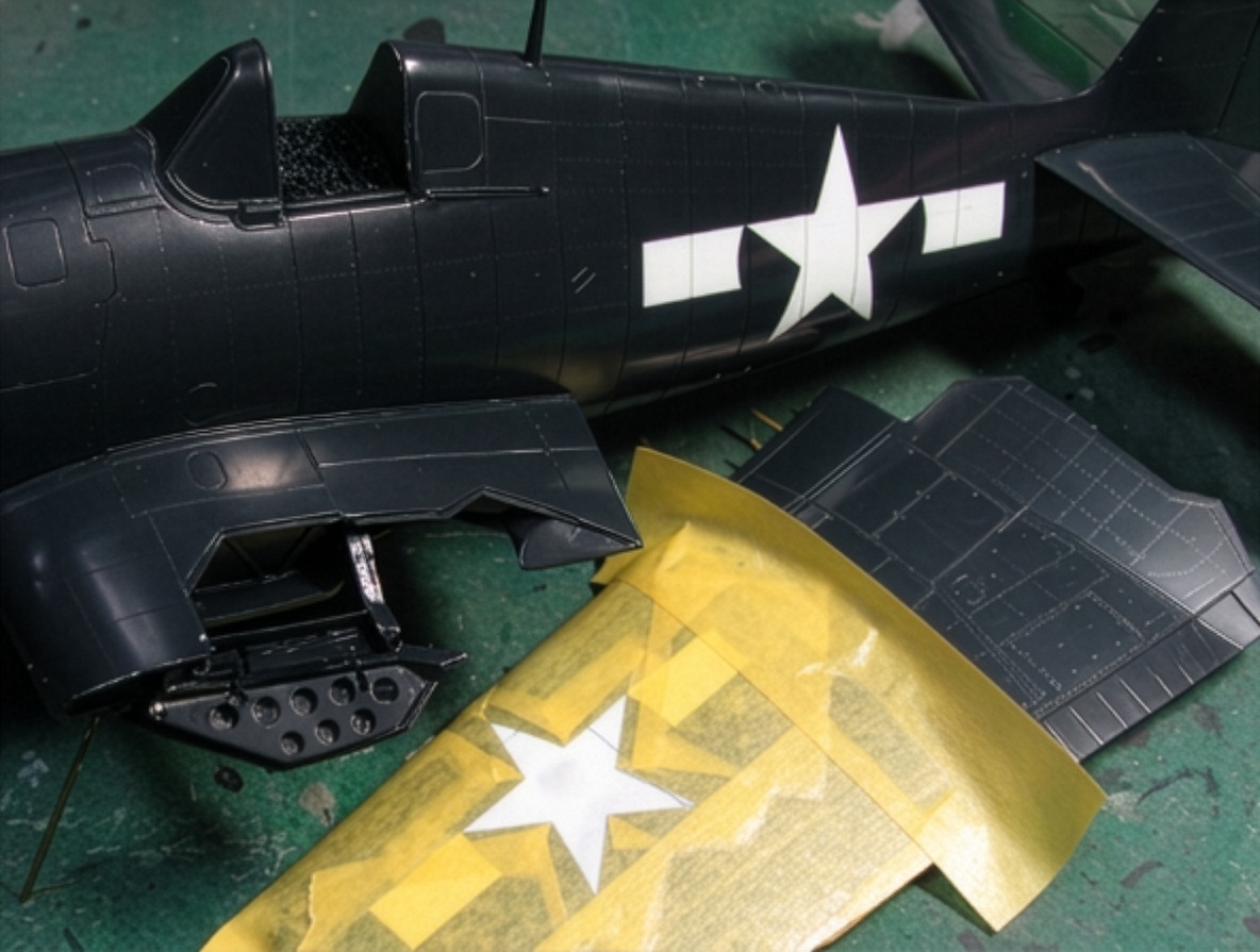
The fuselage national insignia measures approximately 50 inches, based on the diameter of the star.
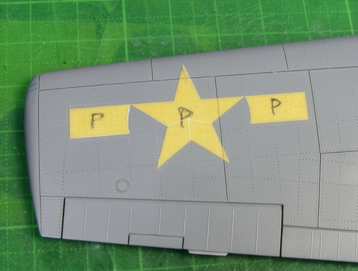
The wing insignia measures approximately 45 inches.
An interesting geometric detail can be seen in the fuselage insignia.
The marking is painted perpendicular to the fuselage frame line on the actual three-dimensional fuselage surface. Consequently, it appears slightly tilted relative to the fuselage reference line when represented in a two-dimensional side-view drawing.
This explains why the white insignia bar and the red fuselage reference line are not parallel in the drawing, even though the fuselage panel line itself is perpendicular to the reference line.
The apparent discrepancy becomes understandable when the three-dimensional surface of the aircraft is considered.
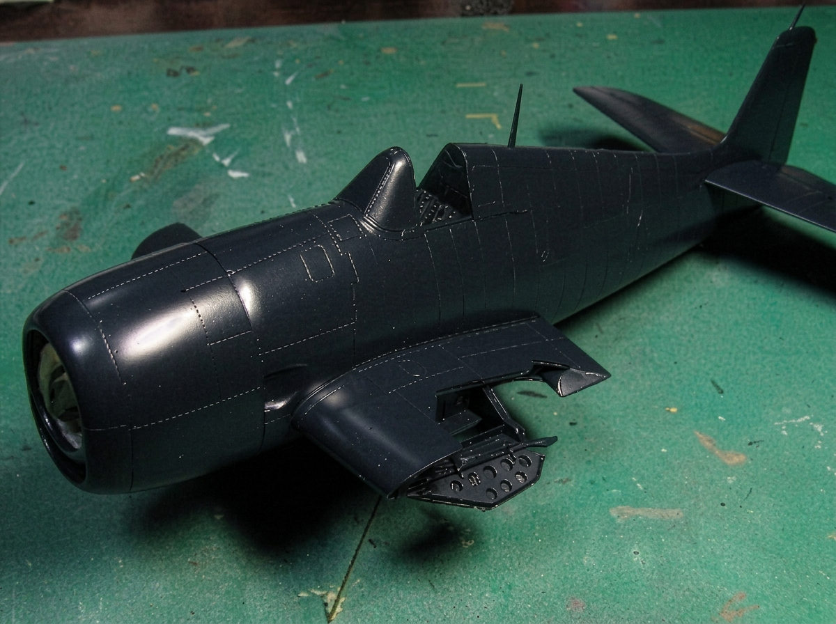
Reproducing Gloss Sea Blue
For the Gloss Sea Blue finish, I mixed Mr. Color No. 365 Gloss Sea Blue with approximately 20% black and a small amount of red.
I did not like the slightly greenish appearance of the straight Mr. Color #365, so the additional colors were used to produce a more convincing blue.
A small amount of flat base was then added to achieve approximately a quarter-satin finish rather than a completely glossy surface.
Before completing the paintwork, the orange-peel texture and the step along the white-and-blue boundary were polished with Mr. Laplos #6000.
The base painting was then completed.
F6F Hellcat Night Fighters: Ultimate Modeling Guide
Completion
After almost a year of construction, the F6F-5 Hellcat “Minsi III” BuNo 70143 was finally completed.
The folding-wing mechanism is not perfect in terms of absolute scale accuracy, and I am not completely satisfied with every detail of its appearance.
However, I am extremely satisfied with its structural rigidity, accuracy of movement and smooth operation.
The use of metal hinges and brass pins connecting the individual wing components made it possible to achieve a mechanism that is both functional and strong enough for repeated movement.
The primary objective of the project was the accurate reproduction of the characteristic contours of the F6F-5 Hellcat.
On that point, I consider the project completely successful.
The wide and powerful cowling, the unmistakable “cat smile,” the sharp windshield, the broad canopy and the massive fuselage finally give the model the visual character of the real aircraft.
After almost a year of construction, corrections, measurements, calculations, scratch-building and historical research, the model finally looks the way I always believed a 1/48 scale F6F-5 Hellcat should look.
And, more importantly, I have fallen in love with the Hellcat all over again.During the research and construction of this Grumman F6F-5 Hellcat, particular attention was given to the aircraft’s wing structure and folding mechanism. The same approach can also be applied when studying other carrier-based aircraft with folding wings, such as the Grumman F6F Hellcat, Grumman F4F Wildcat and Grumman TBF Avenger.
https://soyuyo.main.jp/f6f/f6fgall.html
Gallery